
Method for solving motor vehicle turning left at crossroad

A technology for intersections and motor vehicles, applied to roads, roads, buildings, etc., to achieve low implementation costs, good implementation effects, and small changes

Inactive Publication Date: 2006-05-31
吴斌
View PDF0 Cites 4 Cited by
  • Summary
  • Abstract
  • Description
  • Claims
  • Application Information

AI Technical Summary

Problems solved by technology

This method can solve the problem of motor vehicles turning left at intersections with only a small increase in cost

Method used


Image

  • Method for solving motor vehicle turning left at crossroad
  • Method for solving motor vehicle turning left at crossroad

Examples


Embodiment Construction

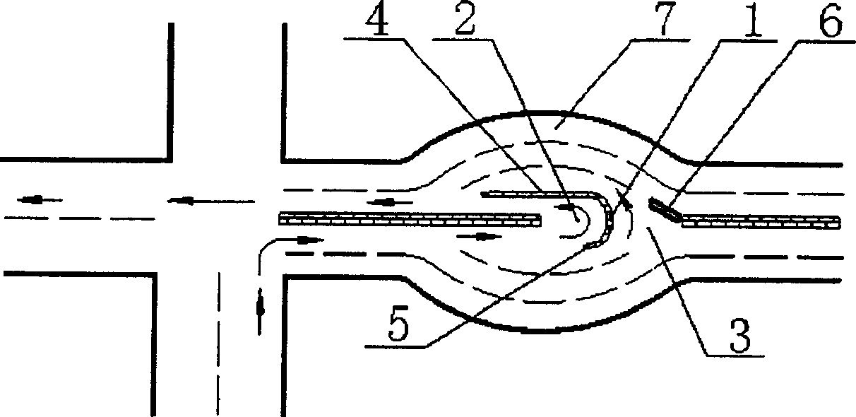
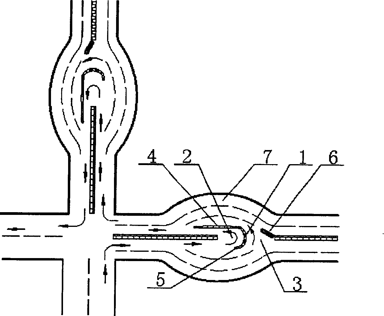
[0010] Examples. The solution to the left turn at the intersection of motor vehicles. Such as figure 1 As shown, on each road at the intersection, select a road section with an appropriate distance from the intersection. Generally, a section that is 50-100 meters away from the intersection is selected, or a section slightly further away. The two sides of the road section are widened separately, and an arc section with a width of not less than one lane and a length of not less than 15 meters is added on both sides to form a widened section 7. A semicircular isolator 1 with a diameter of not less than 8 meters is arranged in the middle of the widened road section. The inner side of the isolator 1 is the turning area 2 for trolleys, and the outer side of the isolator 1 is the turning area 3 for large vehicles. In the meeting positions of the two turning areas, insulators 4, 5, and 6 are respectively arranged. Vehicles that need to turn left figure 1 The route indicated by the arrow...


PUM


Abstract

This is a method for controlling vehicles turning left at a cross. Widen the part of each road on a certain distance to the cross and install a separation facility in the middle. To the inner part of the separation facility is the turning section for small vehicles and to the outer part of the separation facility is the turning section for large vehicles. This method could solve the problem of vehicles turning left with small revamp to present roads at small cost and few impacts to vehicleí»s driving.

Description

Technical field [0001] The invention relates to a method for solving road traffic jams, in particular to a method for solving traffic jams at intersections. technical background [0002] At present, the number of cars in our country is increasing, especially the number of cars in cities has increased significantly. Although all cities have increased their investment in the construction of road traffic facilities, and have significantly improved the conditions of urban road traffic facilities, the phenomenon of urban traffic jams has become more and more serious. In cities, traffic jams mainly occur at intersections. However, the traffic light restriction at intersections is not the main reason for traffic jams. The main reason why vehicles cannot pass the intersection quickly is the left turn of vehicles. A left turn by a vehicle at an intersection not only seriously affects the passing of straight vehicles through the intersection, but also often causes traffic accidents, causin...

Claims


Application Information

Patent Timeline
IPC IPC(8): E01C1/02
Inventor 吴斌
Owner 吴斌
Learn More