Air extraction cylinder

A technology of pumping cylinders and pumping holes, which is applied in the direction of pressurization/vaporization packaging, etc., can solve the problems of reducing the efficiency of vacuuming, increasing the number of pumping times, and poor vacuuming effects, etc., and achieves simple structure and large pumping capacity , the effect of improving efficiency

Inactive Publication Date: 2006-06-14
石正兵
View PDF0 Cites 4 Cited by
  • Summary
  • Abstract
  • Description
  • Claims
  • Application Information

AI Technical Summary

Problems solved by technology

[0002] The air pump currently used to pump air for the vacuum bag, when performing continuous pumping, because the seal is not tight, when the piston is pushed back to prepare for the next pumping, part of the air in the sleeve will flow back into the vacuum bag Waiting for the inside of the package, resulting in an increase in the number of times the piston is pulled to pump air, which reduces the efficiency of vacuuming, and there will always be a part of the air in the package, and the vacuuming effect is poor.

Method used


Image

  • Air extraction cylinder
  • Air extraction cylinder
  • Air extraction cylinder

Examples


Embodiment Construction

[0013] The present invention is further described in detail below in conjunction with the accompanying drawings and specific embodiments:

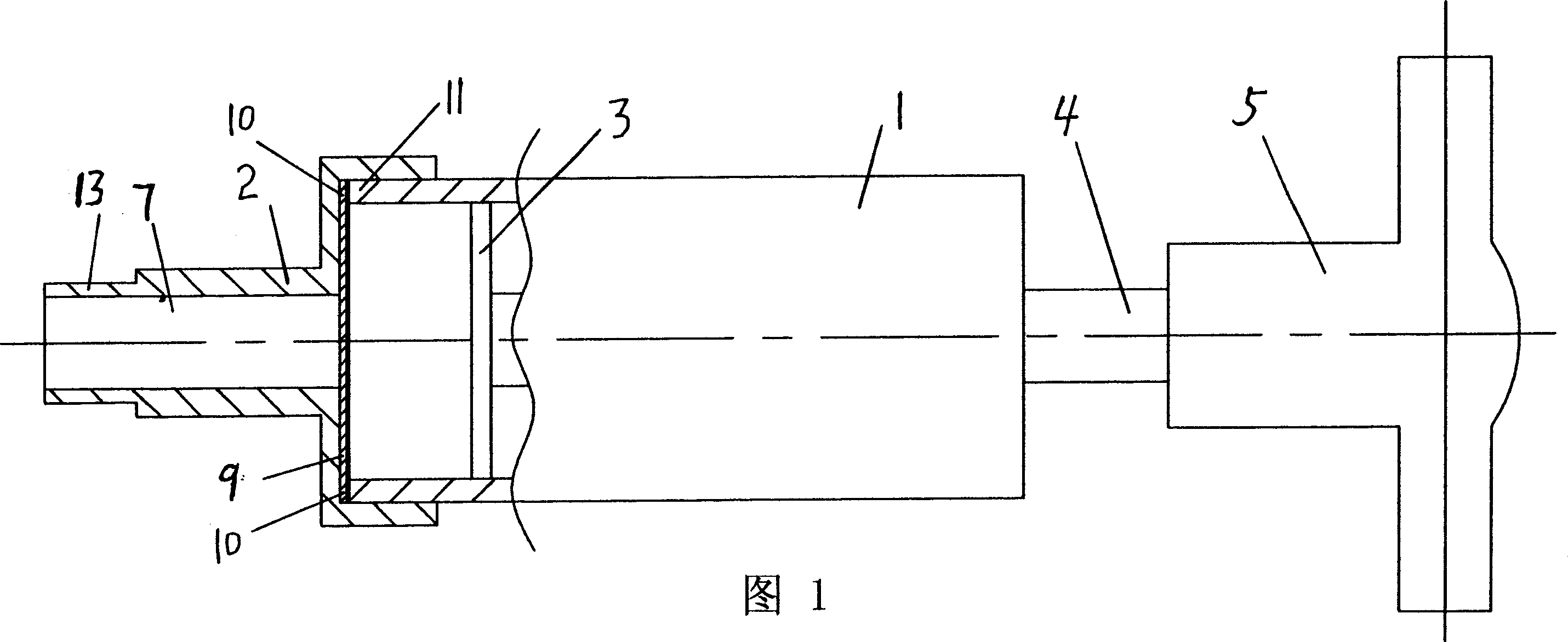
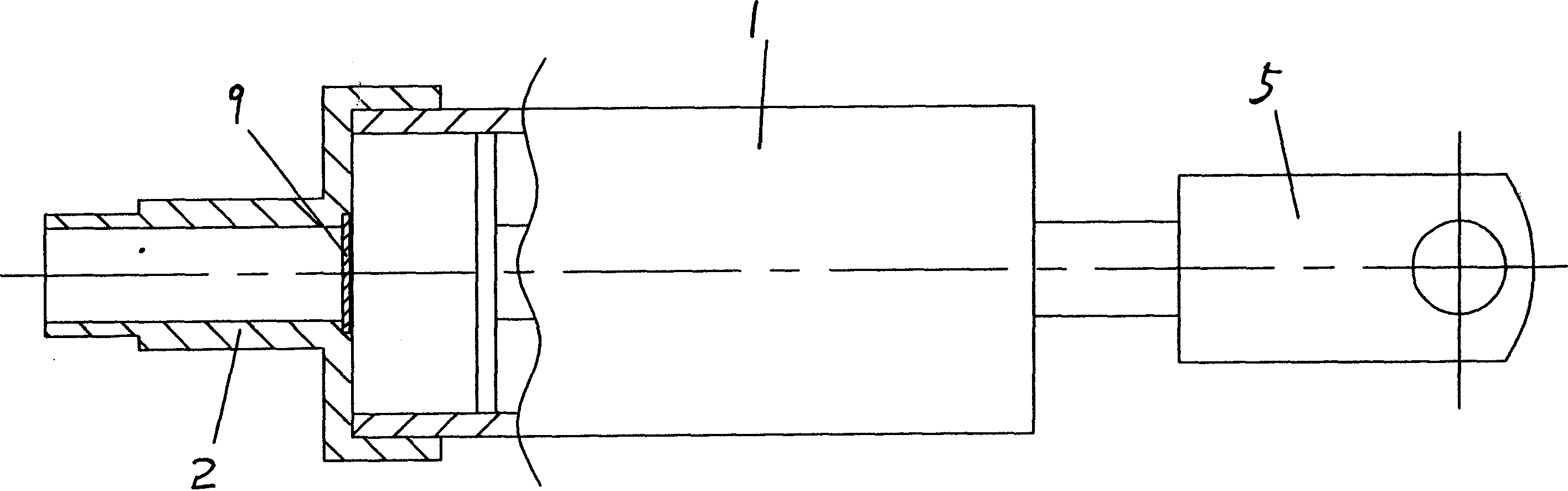
[0014] The present invention includes a sleeve 1 and a nozzle 2 sleeved on the sleeve 1, a piston 3 is installed in the sleeve 1, the piston 3 is connected with the handle 5 through a pull rod 4, and the sleeve is pulled on the handle 5 by hand. The piston 3 in the cylinder 1 is used to pump air.

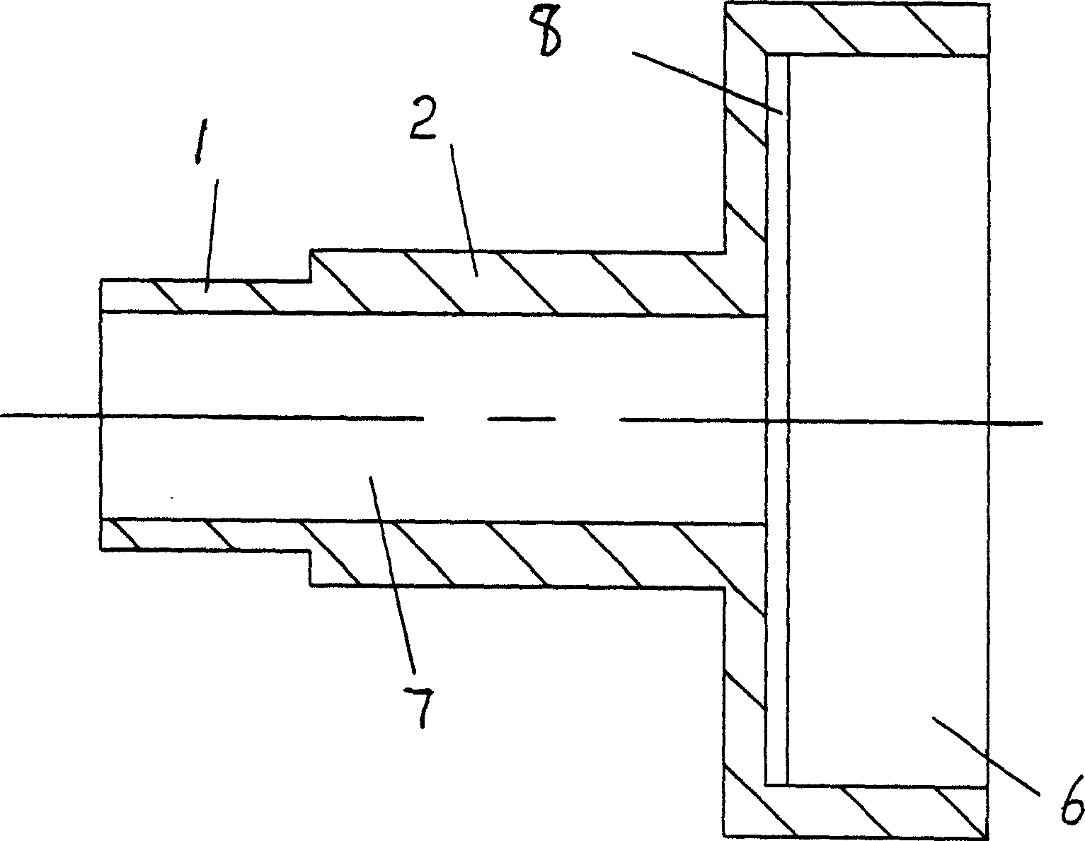
[0015] The sleeve 1 is a hollow cavity, one end of which is pressed into the cavity 6 of the barrel mouth 2, the pull rod 4 is inserted from the other end of the sleeve 1 and connected with the piston 3 in the sleeve 1, and the other end of the pull rod 4 is connected with the piston 3 in the sleeve 1. The handle 5 is connected with the fixed. There is an air extraction hole 7 on the barrel mouth 2. In order to better extract the air in the package such as the vacuum bag, a groove 8 is opened above the air extraction hole 7 at the end of the ba...


PUM


Abstract

The present invention relates to an evacuation tube. It includes the following several portions: sleeve, piston placed in the sleeve, tube mouth, pulling rod and handle. Besides, it also includes an air-resisting piece. Said invention is simple in structure, and can quickly evacuate the package container.

Description

【Technical field】 [0001] The present invention relates to an air extraction cylinder, in particular to an air extraction cylinder used for vacuuming. 【Background technique】 [0002] The air pump that is now used to pump air into the vacuum bag, during continuous pumping, because the sealing plug is not tight, when the piston is pushed back to prepare for the next pumping, part of the air in the sleeve will flow back to the vacuum bag. In the packaging body, the number of times of pulling the piston to pump air increases, which reduces the working efficiency of vacuuming, and there will always be some air left in the packaging body, so the vacuuming effect is poor. [Content of the invention] [0003] The purpose of the present invention is to overcome the deficiencies of the above-mentioned technical problems, and to provide a suction cylinder with a simple structure, high vacuuming efficiency and better vacuuming. [0004] The present invention adopts the following techni...

Claims


Application Information

Patent Timeline
Patent Type & Authority Applications(China)
IPC IPC(8): B65B31/06
Inventor 石正兵
Owner 石正兵
Why Eureka
Try Eureka