Eureka AIR delivers breakthrough ideas for toughest innovation challenges, trusted by R&D personnel around the world.

Improving structure for reflecting cover of electrothermal equipment

A technology of improved structure and electric heating equipment, which is applied in the field of reflectors, can solve the problems of increasing manufacturing and use costs, reducing product service life, and burning of electric heating equipment, and achieves the effects of saving energy, increasing service life, and simple structure

Inactive Publication Date: 2006-06-14
刘志雄
View PDF0 Cites 1 Cited by
  • Summary
  • Abstract
  • Description
  • Claims
  • Application Information

AI Technical Summary

Problems solved by technology

The more obvious the humidification function, the greater the energy consumption, which will undoubtedly increase the cost of manufacturing and use.
The current reflective electric heating equipment (such as electric heaters, etc.), the principle is that the heat energy of the heating element of the electric heating equipment is reflected to the target object through the reflector to achieve the purpose of heating. The greater the power of the heating element, the greater the heat emitted , and the greater the calorific value, the higher the requirements for the material of the electric heating equipment, otherwise it will easily cause the burning of the electric heating equipment
In practical applications, even the heat emitted by the high-power heating element cannot be completely dissipated to the target through the reflector, and this part of the heat will also have a negative impact on the heating equipment while wasting, reducing the The service life of the product

Method used


Image

  • Improving structure for reflecting cover of electrothermal equipment
  • Improving structure for reflecting cover of electrothermal equipment

Examples


Embodiment Construction

[0013] Below in conjunction with a preferred embodiment and accompanying drawing, the present invention will be further described,

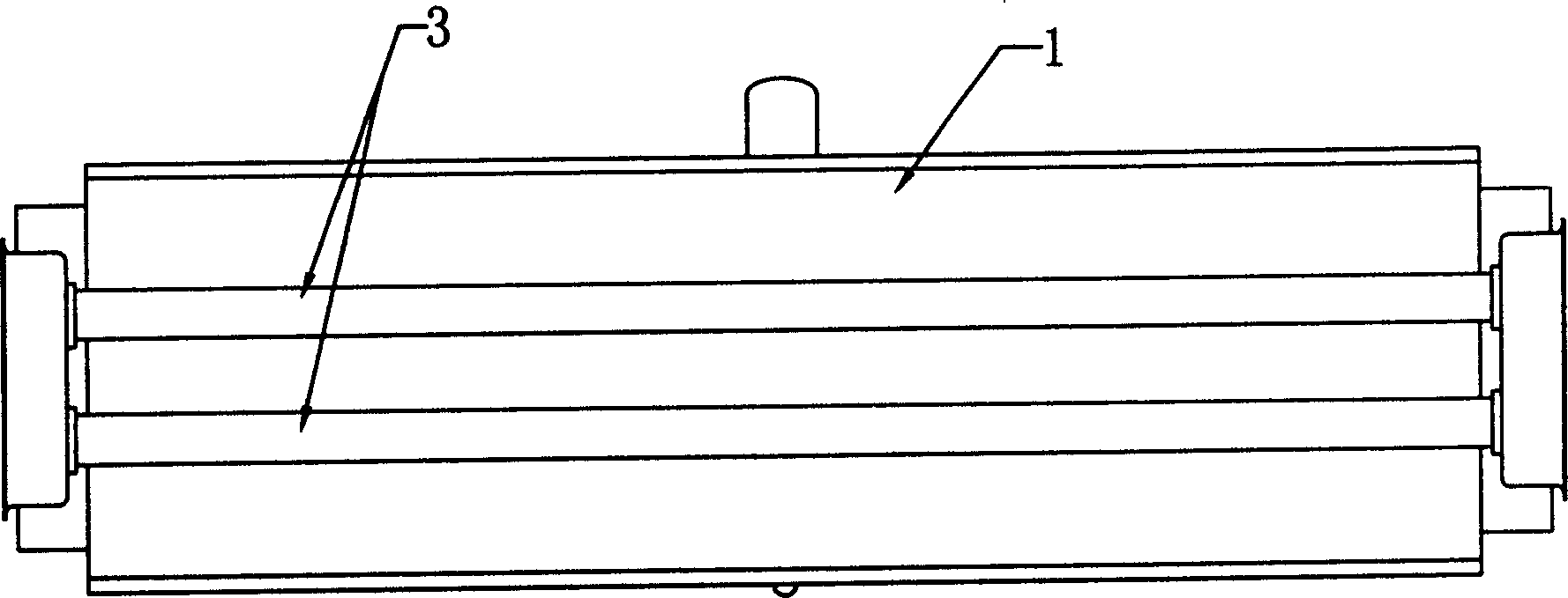
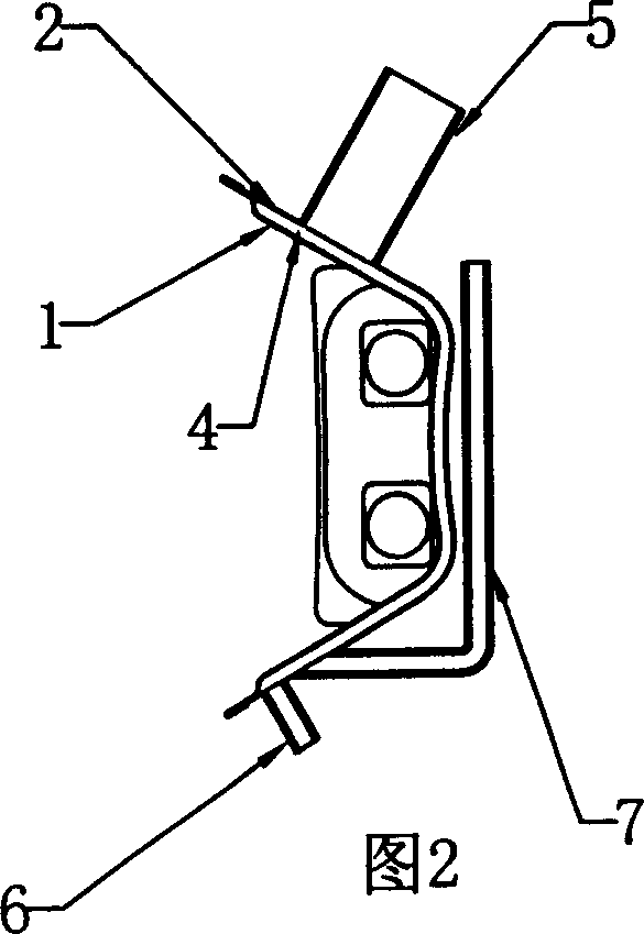
[0014] See attached figure 1 ~As shown in accompanying drawing 2, the preferred reflector of the present invention is installed on one side of the heat pipe 3 of an electric heater by welding the arc-shaped front wall 1 and the arc-shaped rear wall 2, and a wall is formed between the two walls. Cavity 4, an exhaust pipe 5 is welded on the upper part of the rear wall, and a liquid inlet and outlet pipe 6 is installed on the lower part, and the liquid such as liquid can be pumped or directly injected into the cavity 4 horizontally, or can be directly exhausted according to needs. Tube 5 is filled with water. When the electric heater works, the remaining heat evaporates the water in the cavity and other liquids that are beneficial to human health and is discharged into the air by the mouth of the exhaust pipe 5, thereby humidifying the air. In add...


PUM


Abstract

The invention discloses reflecting cover of effectively utilizing electro-heat equipment waste heat to vaporize liquid to humidify air. It is made up front wall and back wall. Cavity body is formed between them. The cavity body can fill evaporable liquid. And its wall body is set exhaust unit. While using, water is injected into the cavity body. The electro-heat equipment is started to make the bowl be heated to heat the water to steam. When the steam reaches certain quantity, it will puff out from the exhaust unit to humidify air. The liquid can be drained away while no need. The operation is simple and convenient.

Description

Technical field: [0001] The invention relates to the technical field of electric heating equipment, in particular to a reflector that effectively utilizes the waste heat of the electric heating equipment to evaporate liquid to humidify the air. Background technique: [0002] Because the use of heating equipment leads to dry air, in order to solve this problem, we have to use humidification equipment or add humidification function to the heating equipment. The more obvious the humidification function, the greater the energy consumption, which will undoubtedly increase the cost of manufacturing and use. The current reflective electric heating equipment (such as electric heaters, etc.), the principle is that the heat energy of the heating element of the electric heating equipment is reflected to the target object through the reflector to achieve the purpose of heating. The greater the power of the heating element, the greater the heat emitted , and the greater the calorific va...

Claims


Application Information

Patent Timeline
Patent Type & Authority Applications(China)
IPC IPC(8): F24F6/10
Inventor 黄应时刘志雄
Owner 刘志雄
Why Eureka
Eureka Blog
Learn More