Guiding device for laying cable and optical cable

A guiding device, optical cable technology, applied in the direction of optical fiber/cable installation, cable laying equipment, etc., can solve problems such as troublesome operation, scrap, cable or optical cable core wire damage, etc., to achieve the effect of convenient operation, avoid falling off, and improve work efficiency

Inactive Publication Date: 2006-06-14
WUXI POWER SUPPLY JIANGSU PROVINCE ELECTRIC POWER +1
View PDF0 Cites 5 Cited by
  • Summary
  • Abstract
  • Description
  • Claims
  • Application Information

AI Technical Summary

Problems solved by technology

Cables or optical cables have sheaths. Once the sheath is damaged, the core wires of the cables or optical cables will be damaged or even scrapped. Therefore, when erecting, they must be guided by pulleys.
In the prior ar

Method used


Image

  • Guiding device for laying cable and optical cable
  • Guiding device for laying cable and optical cable
  • Guiding device for laying cable and optical cable

Examples


Embodiment Construction

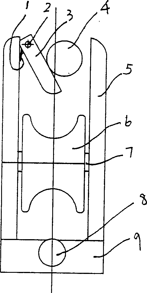
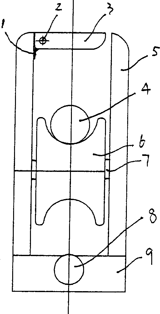
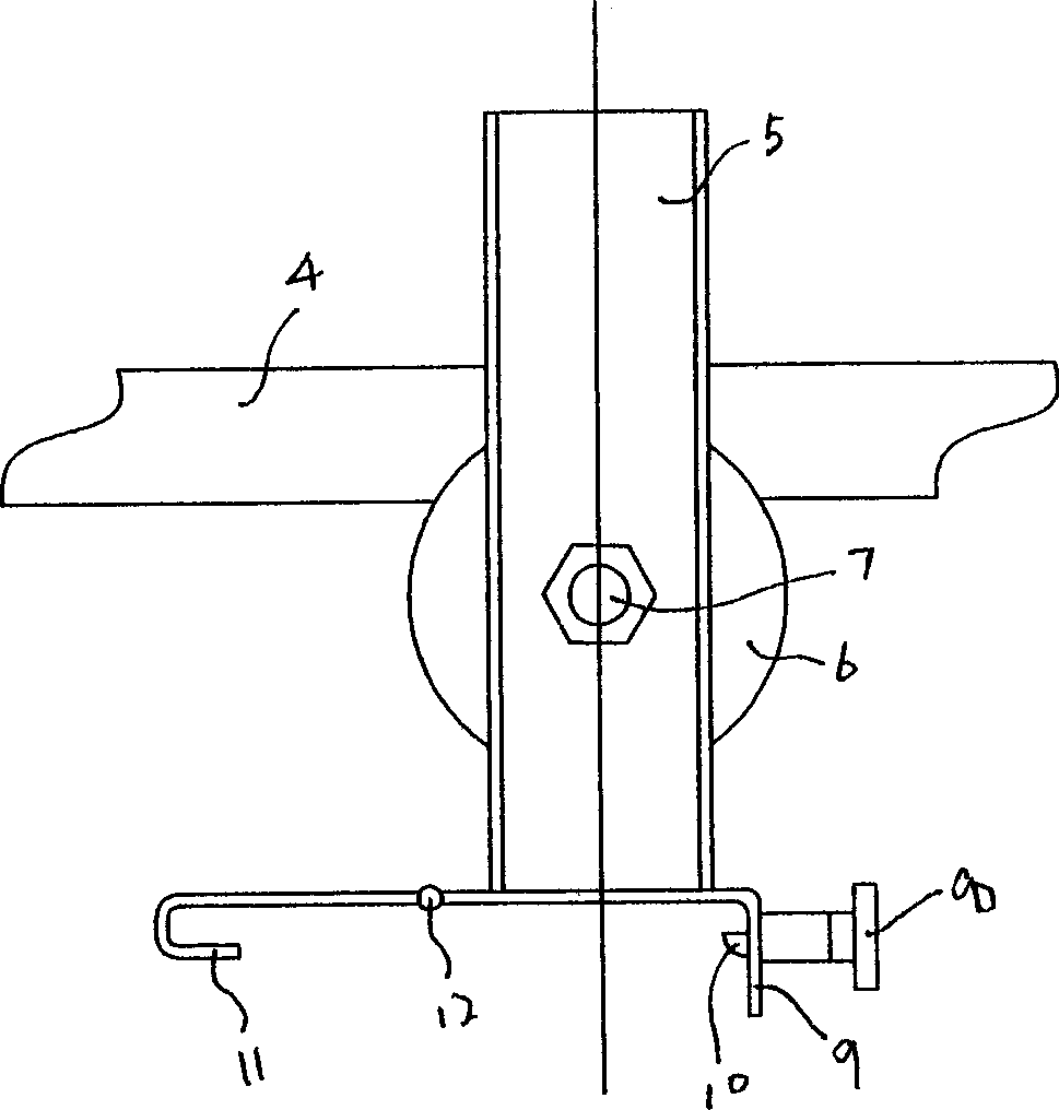
[0012] As shown in the figure: roller 6 is installed on support 5, hinged gusset 15 is hinged at the bottom side of support 5, the baffle plate 9 that extends downwards is arranged on the other side, and hook 11 is arranged at the outer end of gusset 15. During use, put the bottom of the support 5 on the pole tower or the support, then put the buckle plate 15 down, and make the hook 11 on the buckle plate 15 hook up a certain position of the pole tower or the support, and the hook 11 on the buckle plate 15 and the baffle plate 9 Under the joint action, the pulley is fixed on the tower or support.

[0013] If necessary, a positioning mechanism can be connected to the outside of the baffle plate 9. In the positioning mechanism, the sleeve 13 is installed on the outside of the baffle plate 9, and a pull rod 14 is arranged in the sleeve 13, and the handle 8 is connected to the outer end of the pull rod 14, and the pull rod 14 There is a tongue piece 10 at the inner end of the slee...


PUM


Abstract

This invention relates to a pilot device for laying cables, in which, an idler wheel is mounted on the frame according to the invented design characterizing in splicing a pinch plate at a side of the bottom of the frame and a baffle extending downwards at the other side, a sleeve is connected at the outside of the baffle, a pull rod is in the sleeve, a handle is set at the outer end of the pull rod and a tongue passing through the baffle is in the inner end of the rod and a spring for resetting the rod is in the sleeve.

Description

technical field [0001] The invention relates to a tool used for erecting electrical or optical cables. Background technique [0002] When erecting electric cables or optical cables, it is necessary to pull out the electric cables or optical cables from the reel, and then erect them on the installed towers or supports. Cables or optical cables have sheaths. Once the sheath is damaged, the core wires of the cables or optical cables will be damaged or even scrapped. Therefore, when erecting, pulleys must be used to guide them. In the prior art, this kind of pulley is only a rotatable roller installed in a simple bracket. When the pulley is fixed on a certain part of the tower or bracket, it needs to be fixed by another device, which is troublesome to operate. . Contents of the invention [0003] The object of the present invention is to design a guide device for laying cables and optical cables, and to improve work efficiency and erection quality by setting a positioning me...

Claims


Application Information

Patent Timeline
IPC IPC(8): H02G1/06G02B6/46
Inventor 董寿洪
Owner WUXI POWER SUPPLY JIANGSU PROVINCE ELECTRIC POWER
Why Eureka
Try Eureka