Infrared touch device

An infrared touch and infrared receiving technology, which is applied in the direction of instruments, electrical digital data processing, data processing input/output process, etc., can solve the problems of increasing manufacturing costs, eliminate blind spots, increase detection areas, and reduce costs. Effect

Inactive Publication Date: 2006-06-28
GUANGDONG VTRON TECH CO LTD
View PDF0 Cites 25 Cited by
  • Summary
  • Abstract
  • Description
  • Claims
  • Application Information

AI Technical Summary

Problems solved by technology

Although this method can improve the focusing performance of the infrared element to a certain extent, it also increases the manufacturing cost

Method used


Image

  • Infrared touch device
  • Infrared touch device
  • Infrared touch device

Examples


Embodiment Construction

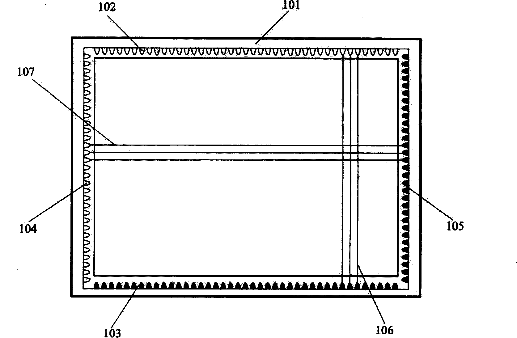
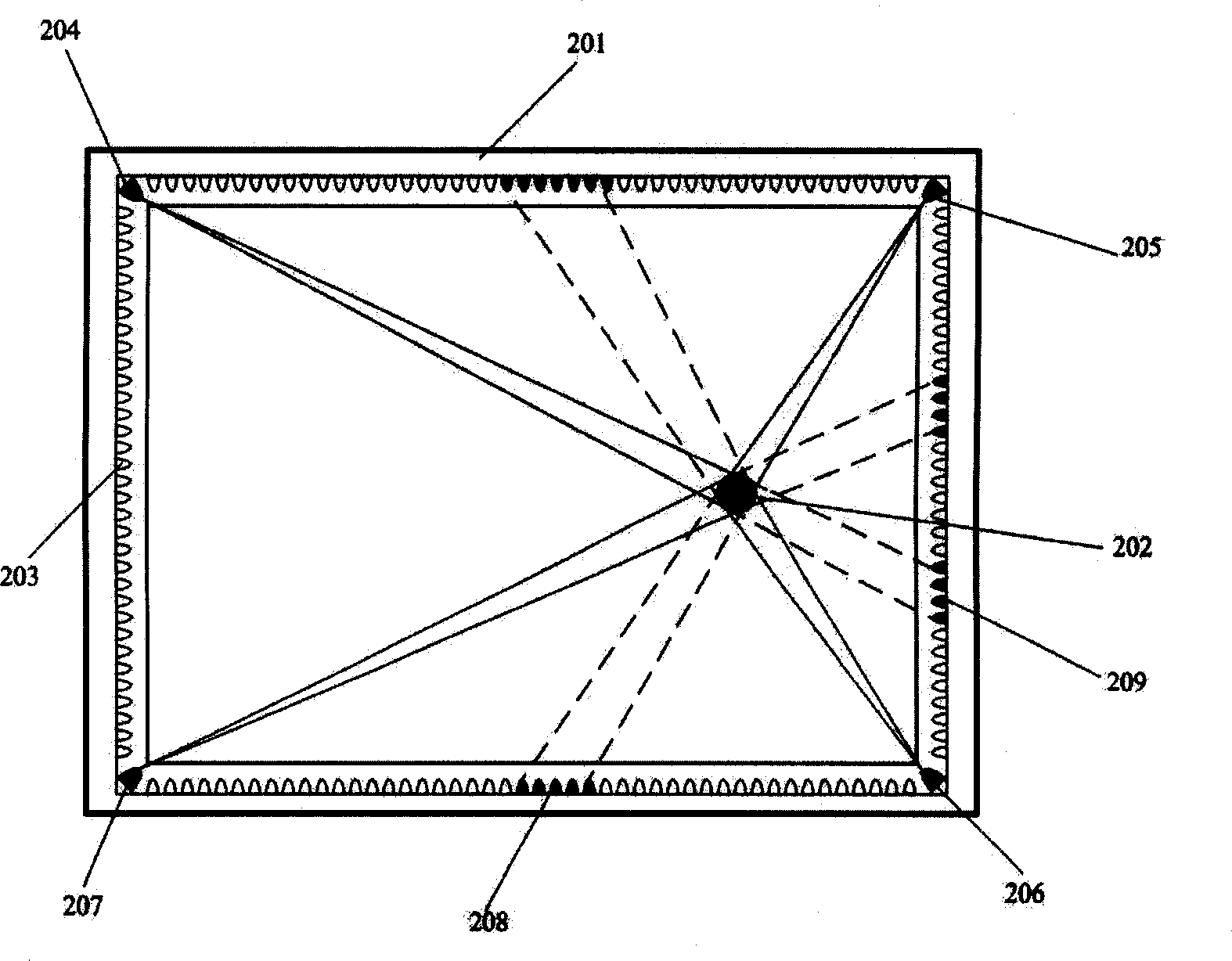
[0036] Please refer to figure 2, is an embodiment of the present invention, the infrared receiving element 203 is arranged around the frame 201, and the four infrared emitting elements 204, 205, 206, 207 are respectively arranged on the upper left, upper right, lower right, and lower left of the frame 201. In a corner, when the operating body 202 enters the detection area, the cone-shaped infrared beam emitted by the infrared emitting element 204 in the upper left corner is partially blocked by the operating body 202, so that the output signals of the receiving element 209 and several adjacent receiving elements change; The cone-shaped beam emitted by the infrared emitting element 205 in the upper right corner is also partially blocked by the operating body 202, so that the output signals of the receiving element 208 and several adjacent receiving elements change, and the cone-shaped beam emitted by the infrared emitting element in other corners It will also be occluded to va...


PUM


Abstract

An infrared touch device consists of driving circuit, signal processing circuit, infrared emitting element, infrared receiving element and detection region. It features that there are infrared emitting element and also infrared receiving element on at least two side edges at periphery of detection region, infrared ray emitted by each infrared element is always received by multiple infrared receiving units.

Description

【Technical field】 [0001] The invention relates to an infrared touch system or a touch screen, in particular to an infrared touch device used as a wireless input device. 【Background technique】 [0002] Generally speaking, for an infrared touch system or a touch screen, the determination of the touch position is determined by an infrared emitting element and an infrared receiving element. The operating body can be a finger or a pencil, etc., and the input operation can be performed only by going deep into the frame to block the infrared light. In principle, the detection does not require the operating body to be in contact with any screen. [0003] For the principle and composition of the infrared touch system, there have been a number of Chinese patents, and there are many foreign documents that introduce this technology in detail, so I won't repeat them here. [0004] In the prior art infrared touch system, the number of emitting elements arranged around the screen is equa...

Claims


Application Information

Patent Timeline
Patent Type & Authority Applications(China)
IPC IPC(8): G06F3/042
Inventor 卢如西李军明
Owner GUANGDONG VTRON TECH CO LTD
Why Eureka
Try Eureka