Active damping control for a switch mode power supply

A switch-mode power supply, switching technology, applied in control/regulation systems, circuits, electrical components, etc., can solve problems such as low efficiency and inability to maintain high efficiency

Active Publication Date: 2006-07-05
HANGZHOU MPS SEMICON TECH
View PDF0 Cites 10 Cited by
  • Summary
  • Abstract
  • Description
  • Claims
  • Application Information

AI Technical Summary

Problems solved by technology

Known "buck-boost" converters can operate automatically with input voltages greater than, less than, or equal to the output voltage, but cannot maintain high efficiency over a wide range of input voltages
The buck-boost converter has proper efficiency only when the input voltage is close to the output voltage, but when the input voltage is greater than the output voltage, the buck-boost converter is much less efficient than the buck converter, and When the input voltage is less than the output voltage, the efficiency of the buck-boost converter is much lower than that of the boost converter

Method used


Image

  • Active damping control for a switch mode power supply
  • Active damping control for a switch mode power supply
  • Active damping control for a switch mode power supply

Examples


Embodiment Construction

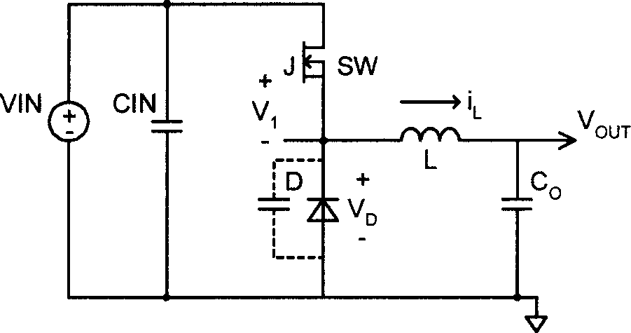
[0046] Embodiments disclosed herein use actively controllable damping devices, such as controllable resistors, current sources, and tri-state power devices, to achieve proper damping and minimize power loss.

[0047] Various embodiments of the invention will be described. The following description provides specific details for a thorough understanding and enabling implementation of the described embodiments. However, it will be understood by those skilled in the art that the present invention may be practiced without many of these details. In addition, some well-known structures or functions may not be described in detail to avoid redundant descriptions and make the related descriptions of the various embodiments unclear.

[0048] Terms in the following description should be interpreted in the broadest manner reasonable, even when used in connection with a detailed description of a particular embodiment of the invention. Certain terms may be further emphasized below; however...


PUM


Abstract

Methods and apparatus are disclosed for suppressing circuit noise due to parasitic elements in switch mode power supplies. The presented embodiments use actively controlled damping devices such as controllable resistors, current sources, and tri-state power devices to achieve required damping and to minimize power loss.

Description

[0001] Cross References to Related Applications [0002] This application claims priority to US Provisional Patent Application No. 60 / 639,739, filed December 28,2004. technical field [0003] Embodiments of the invention described below relate generally to switch mode power supplies and switching regulators, and more particularly to methods and apparatus for suppressing circuit noise caused by parasitic elements. Background technique [0004] Due to their high efficiency, switched-mode power supplies (SMPS) are widely used in power electronic circuits, such as CPUs, DRAMs, and ASICs. Unlike a power device used in a linear regulator, a power device in an SMPS functions as an on (ON) or off (OFF) switching element. Therefore, conduction power loss can be minimized. However, the switching action of these power devices will often result in unwanted high frequency oscillations due to at least one of the following reasons: [0005] a. Parasitic inductance in circuit board layou...

Claims


Application Information

Patent Timeline
Patent Type & Authority Applications(China)
IPC IPC(8): H02M3/155
CPCH02M1/34H02M3/155H02M2001/344H03K17/08142H02M1/344H02M3/28
Inventor 徐鹏
Owner HANGZHOU MPS SEMICON TECH
Why Eureka
Try Eureka