Air current circulation aircraft and method for making the same
A technology of circulating airflow and realization method, applied in the field of aviation aircraft, can solve the problems of high energy consumption, low aircraft lift, and high control difficulty, and achieve the effects of good safety, less space, and good economy.
- Summary
- Abstract
- Description
- Claims
- Application Information
AI Technical Summary
Problems solved by technology
Method used
Image

Examples
Embodiment 1
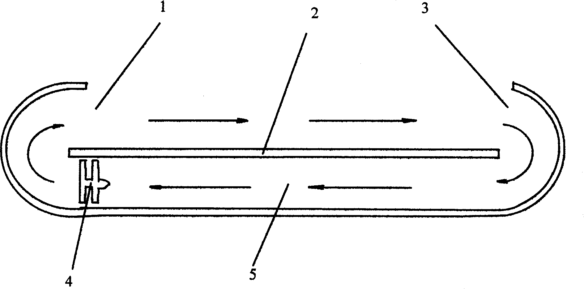
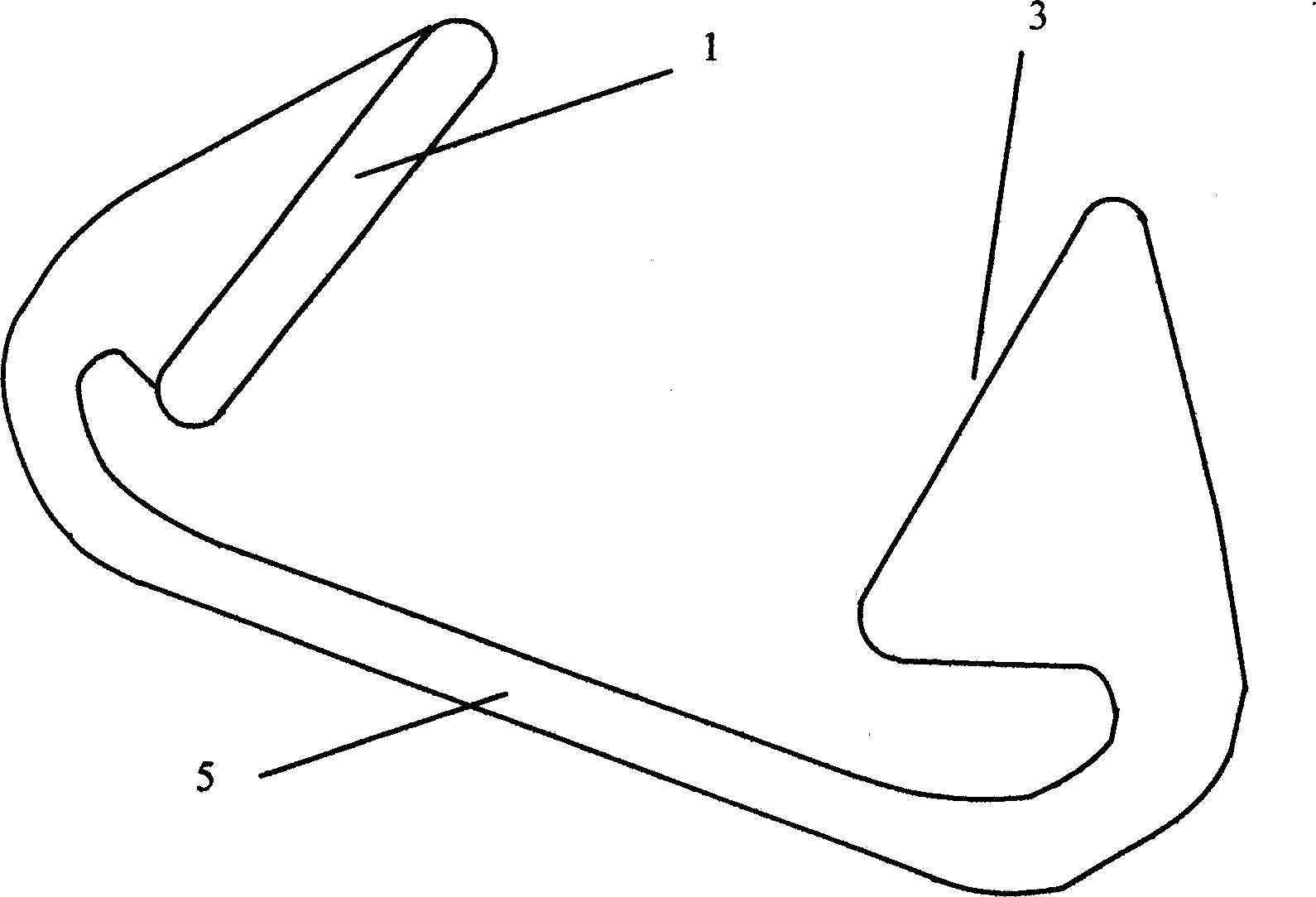
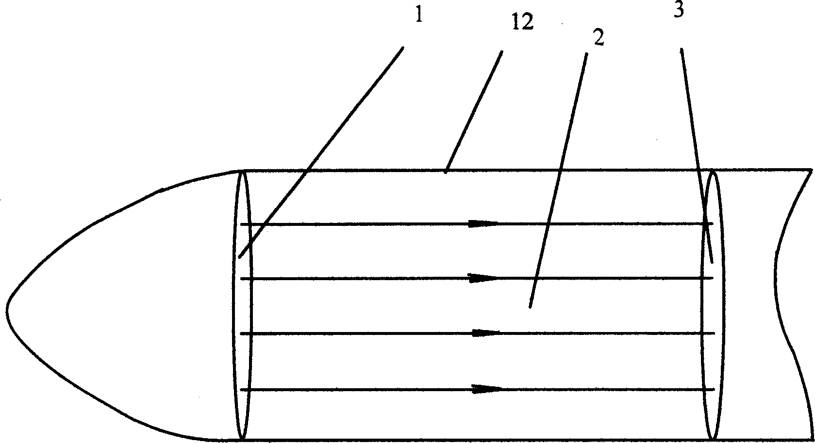
[0016] A circulating airflow system is provided on the aircraft, that is, a channel 5 is arranged in the aircraft, and a compressor 4 is arranged in the channel 5. The two ports of the channel 5, namely the air outlet 1 and the air inlet 3, are exposed above the aircraft. The two ports are Opposite and have a certain distance, between the two ports is the upper surface 2 of the aircraft, its structure can refer to image 3 . The air compressor 4 accelerates the airflow in the channel 5 or flows at a constant speed, and flows out from the air outlet 1, passes through the upper surface 2 of the aircraft, and then flows into the channel 5 from the air inlet 3, and is then accelerated by the compressor, and the cycle continues like this . The airflow that flows out from the air outlet 1 and flows through the upper surface 2 of the aircraft reduces the pressure on the upper surface of the aircraft. When the flow velocity of the airflow is sufficient to make the pressure on the low...
Embodiment 2
[0018] In order to make the aircraft have more manned or cargo space, the ports of the channel 5 can be distributed above the two sides of the aircraft, and the passenger compartment 6 is in the middle, such as Figure 5 shown. At this time, the passage 5 can be divided into two branch pipes 7, so that the top of the aircraft both sides has an airflow to flow through, generating lift, as Image 6 shown. Certainly also can adopt left and right two independent circulation airflow systems to realize take-off. Because the lift of the aircraft is mainly used on the lower surface of the aircraft, and the gravity acts on the inside of the aircraft, that is, the point of action of gravity is above the point of action of the lift, so the stability of the aircraft is relatively poor. To make the stability of the aircraft better, The lower surfaces on both sides of the aircraft can be concave upwards, so that the point of action of the lift force can be raised to increase the stability...
Embodiment 3
[0020] Using the method of the present invention on the car is to set the airflow circulation system on the car, which can make the car realize flying, making it the best flying car in performance today. In order to make the flying car have more space for people or cargo, the ports of the channel 5 can be divided into both sides of the flying car like in Embodiment 2, and the passenger cabin 6 is in the middle, such as Figure 7 shown.
PUM
 Abstract
Description
Claims
Application Information
 - R&D
- Intellectual Property
- Life Sciences
- Materials
- Tech Scout
- Unparalleled Data Quality
- Higher Quality Content
- 60% Fewer Hallucinations
Browse by: Latest US Patents, China's latest patents, Technical Efficacy Thesaurus, Application Domain, Technology Topic, Popular Technical Reports.
© 2025 PatSnap. All rights reserved.Legal|Privacy policy|Modern Slavery Act Transparency Statement|Sitemap|About US| Contact US: help@patsnap.com