

Connector for connecting two pipes
A technology of connecting parts and connecting pieces, which is applied in the direction of mechanical equipment, couplings, etc., and can solve problems such as unsealed connections
- Summary
- Abstract
- Description
- Claims
- Application Information
AI Technical Summary
Problems solved by technology
Method used
Image

Examples
Embodiment Construction
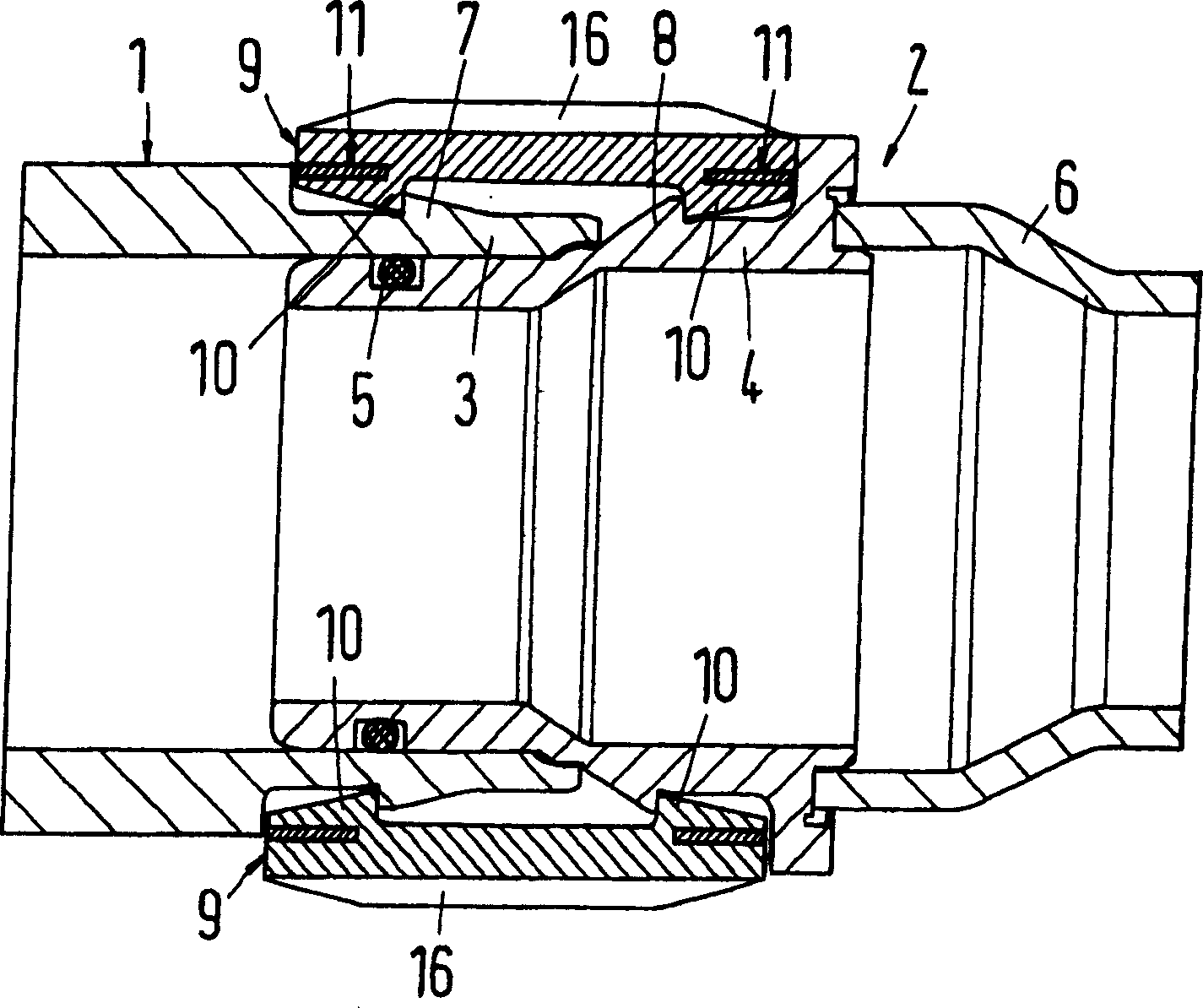
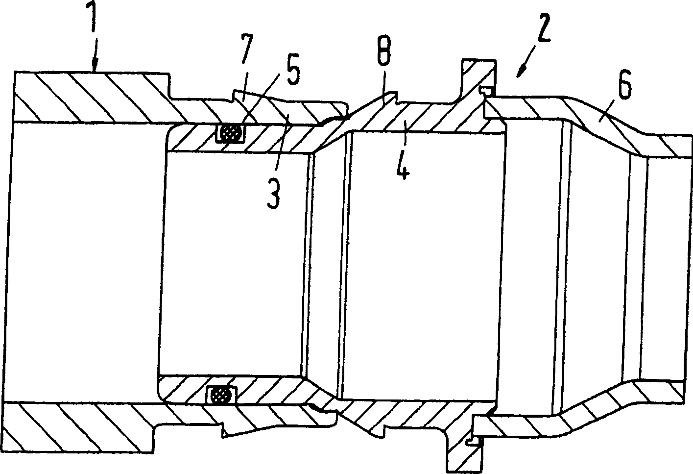
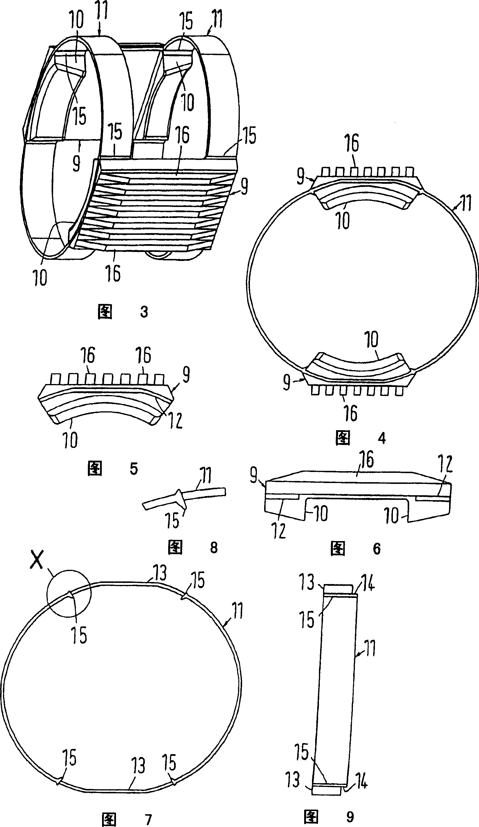
[0058] figure 1 Embodiments of connectors and parts thereof according to the present invention are shown in and 3-9. This connecting piece is used to connect two pipes 1 and 2, only partially shown, made of thermoplastic material or metal. Tubes 1 and 2 are in figure 2 Connectors are not shown. The end sections 3 and 4 of the tubes 1 and 2 are inserted into the connector and joined together. The region where the end sections 3 and 4 join each other is sealed relative to each other by a sealing ring 5 . The end section 4 is welded to the remainder 6 of the tube 2 . Each end section 3 and 4 has an annular positioning rib 7 or 8 respectively.
[0059] The connecting piece has a radially inwardly protruding positioning lug 10 at the axial end of the bending-rigid connecting piece 9 . The positioning lugs 10 lock or snap behind the positioning ribs 7 and 8 when the end sections 7 and 8 are inserted into the connecting piece and are simultaneously joined together. For this p...
PUM
 Abstract
Description
Claims
Application Information