Ultraviolet irradiation apparatus

An irradiation device and ultraviolet technology, which is applied in the direction of lighting devices, measuring devices, nonlinear optics, etc., can solve problems such as inability to reliably detect non-lighting

Active Publication Date: 2011-04-27
USHIO DENKI KK
View PDF2 Cites 0 Cited by
  • Summary
  • Abstract
  • Description
  • Claims
  • Application Information

AI Technical Summary

Problems solved by technology

At this time, if a photodetector is arranged at a portion corresponding to the Y region, the visible light radiated from the Y region and converted by the phosphor layer 78 can be detected by the photodetector 77, although the X region is not lit. Therefore, the operator who operates the ultraviolet irradiation device may mistakenly think that the excimer lamp is turned on as usual, and there is a problem that non-lighting in the X area cannot be reliably detected.

Method used


Image

  • Ultraviolet irradiation apparatus
  • Ultraviolet irradiation apparatus
  • Ultraviolet irradiation apparatus

Examples


no. 1 approach

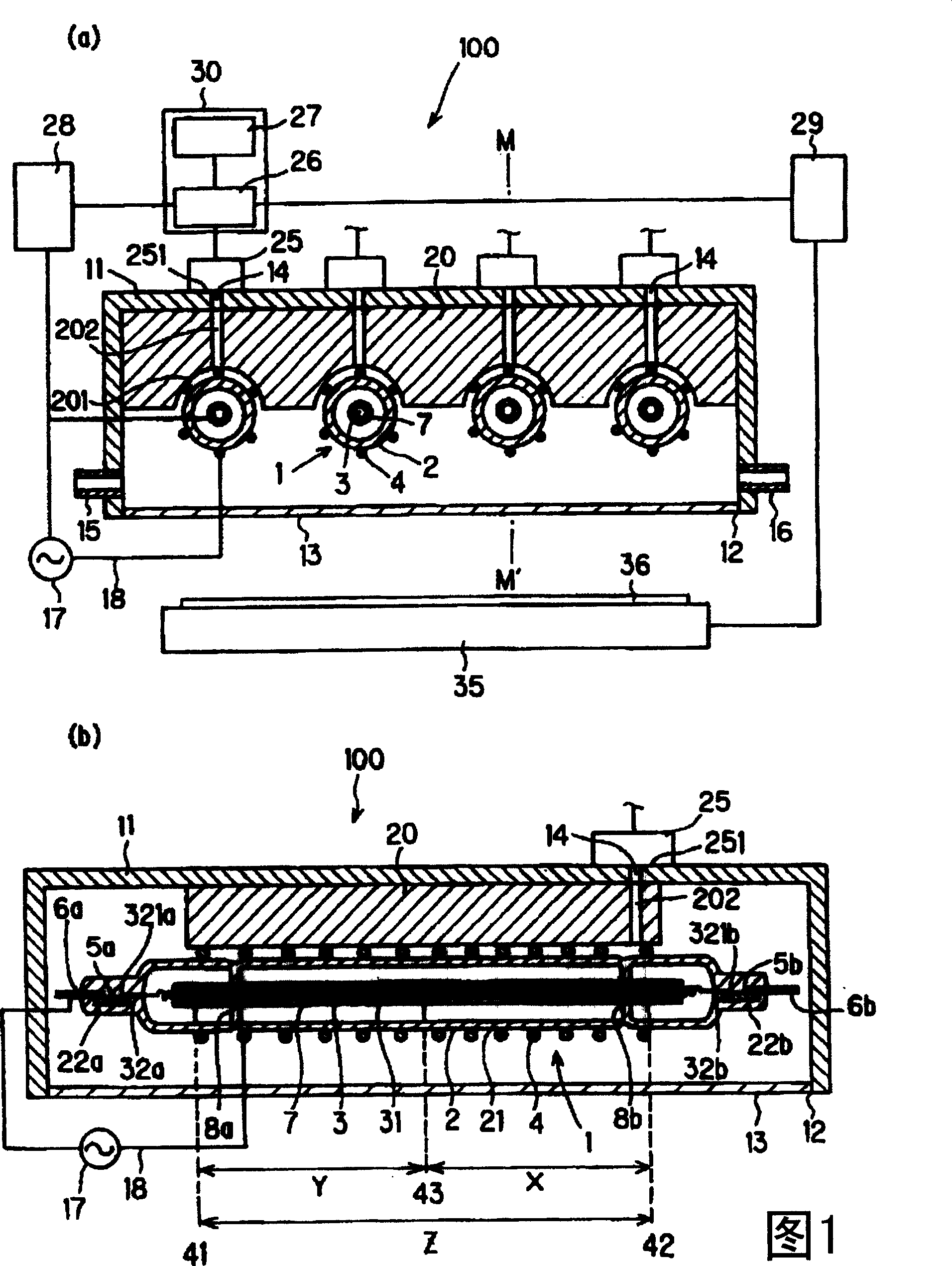
[0041] Fig. 1 is a cross-sectional view showing a first ultraviolet irradiation device of the present invention. FIG. 1( a ) is a cross-sectional view showing the ultraviolet irradiation device taken along a plane perpendicular to the tube axis of the excimer lamp. Fig. 1(b) is a cross-sectional view showing the ultraviolet irradiation device shown in Fig. 1(a) cut along the tube axis direction of the excimer lamp on a plane including the M-M' line.

[0042] The ultraviolet irradiation device 100 accommodates four excimer lamps 1 having a single-layer cylindrical structure in a box-shaped frame 11 and is arranged to face a substrate 36 , which is an object to be processed, placed on a transport mechanism 35 .

[0043] A light extraction window member 13 made of, for example, quartz glass for extracting vacuum ultraviolet light from the excimer lamp to the outside is disposed in the opening 12 of the housing 11 . A through-hole 14 is formed at a position above the excimer lamp...

no. 2 Embodiment approach

[0082] Figure 5 It is a cross-sectional view showing the second ultraviolet irradiation device of the present invention taken along a plane including the tube axis of the excimer lamp. The same symbols as those in Fig. 1 indicate the same or corresponding parts. The ultraviolet irradiation device 500 has the same structure as the ultraviolet irradiation device shown in FIG. 1 except that the excimer lamp 50 having a double-tube structure is used.

[0083] The excimer lamp 50 has a discharge vessel 55 having a double-tube structure. The discharge vessel 55 includes a cylindrical outer tube 51 made of a dielectric such as quartz glass and having an outer diameter smaller than the inner diameter of the outer tube 51. For example, a cylindrical inner tube 52 made of a dielectric such as quartz glass, and side wall portions 53, 54 that airtightly seal the two ends of the cylindrical space formed by the outer tube 51 and the inner tube 52; The cylindrical discharge space S formed...

no. 3 Embodiment approach

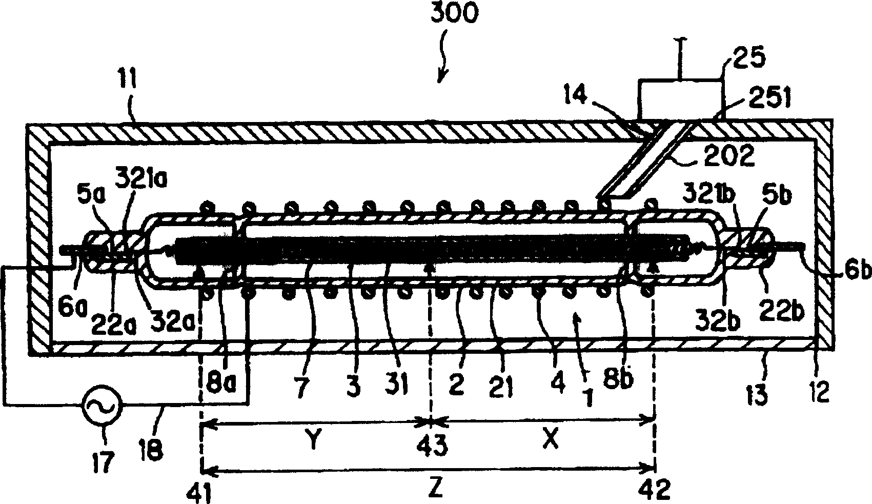
[0088] Fig. 6 is a cross-sectional view of the third ultraviolet irradiation device of the present invention taken along a plane including the tube axis of the excimer lamp. The same symbols as in Fig. 1 indicate the same or corresponding parts.

[0089] Both the external lead wires 6 a and 6 b of the ultraviolet irradiation device 600 and the external electrode 4 are connected to the power supply device 17 through the power supply line 18 . The area near the center of the effective light-emitting area Z (the following Figure 7 Corresponding to the area indicated by the V line in the above, the light guide part 202 penetrating the cooling member 20 in the vertical direction is formed correspondingly, and the light receiving part 25 is placed on the on frame 11. The "region near the center" refers to a position where the light receiving unit 25 can observe the center of the excimer lamp. Except for these points, other configurations are the same as those of the ultraviolet ...


PUM

PropertyMeasurementUnit
lengthaaaaaaaaaa
lengthaaaaaaaaaa

Abstract

The invention provides an ultraviolet irradiation device which has an excimer lamp and can surely detect whether the excimer lamp is lit up or not. The ultraviolet irradiation device is provided with a discharge container, an excimer lamp and a power supply device, wherein, at least part of the discharge container is formed by dielectric medium material which can transmit ultraviolet rays and gasfor discharging is filled in the inner discharging space; the excimer lamp is provided with a pair of electrodes which are arranged face to face across the dielectric medium material of the dischargecontainer; the power supply device is connected with the pair of electrodes and used to supply the excimer lamp with power. The ultraviolet irradiation device is characterized in that the power supply device is connected electrically with at least one end of any electrode. The ultraviolet irradiation device is provided with a light guiding part, a light receiving part and a lightingup detecting component, wherein, in an effective lighting area, the light guiding part is configured correspondingly in the area which is more closer to the other end of the electrode than the end connected with the power supply device, so that the light which is emitted by the excimer lamp and entered from one end of the electrode can be emitted from the other end; the light receiving part is used to receive the light emitted from the light guiding part.

Description

technical field [0001] The present invention relates to an ultraviolet irradiation device equipped with an excimer lamp. In particular, it relates to an ultraviolet irradiation device that measures the intensity of radiated light from an excimer lamp, and checks the lighting state of the excimer lamp based on the measurement result. Background technique [0002] In the manufacturing process of liquid crystal substrates, etc., active oxygen generated by ozone decomposition is applied to the substrate being conveyed to treat the object to be processed. This ozone is generated by irradiating oxygen with ultraviolet light with a wavelength of 200 nm or less. For example, a cleaning technology for removing organic matter adhering to the substrate surface has been put into practical use. [0003] As a lamp for such a treatment, a low-pressure mercury lamp emitting vacuum ultraviolet rays having a wavelength of 185 nm has been used conventionally. [0004] In recent years, instea...

Claims


Application Information

Patent Timeline
Patent Type & Authority Patents(China)
IPC IPC(8): H01J65/00G01J1/00G02F1/13
CPCH01J5/50H01J65/046H05B41/2806H05B41/36
Inventor 广濑贤一
Owner USHIO DENKI KK
Why Eureka
Try Eureka