Ground socket device

A technology of floor and cover plate, applied in the direction of base/casing, installation of connecting parts, electrical components, etc., can solve the problems of difficult movement of wiring and difficult operation, and achieve the effect of preventing position deviation, improving appearance and simplifying connection operation.

Active Publication Date: 2006-07-26
MATSUSHITA ELECTRIC WORKS LTD
View PDF0 Cites 3 Cited by
  • Summary
  • Abstract
  • Description
  • Claims
  • Application Information

AI Technical Summary

Problems solved by technology

In this case, since the wiring passes through the opening of the co

Method used


Image

  • Ground socket device
  • Ground socket device
  • Ground socket device

Examples


Embodiment Construction

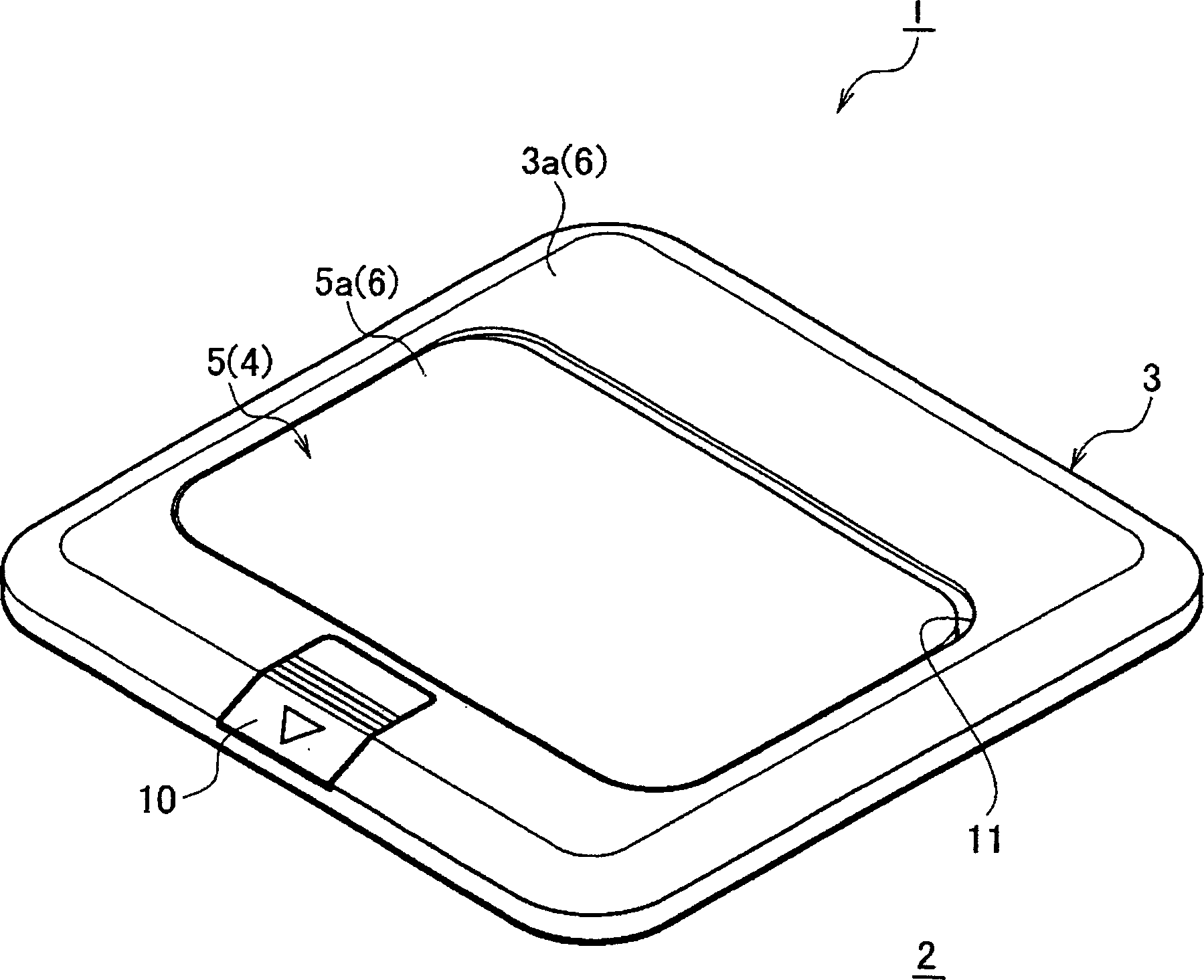
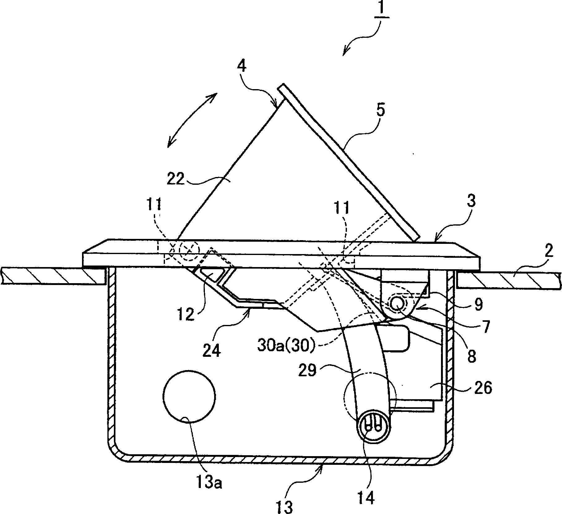
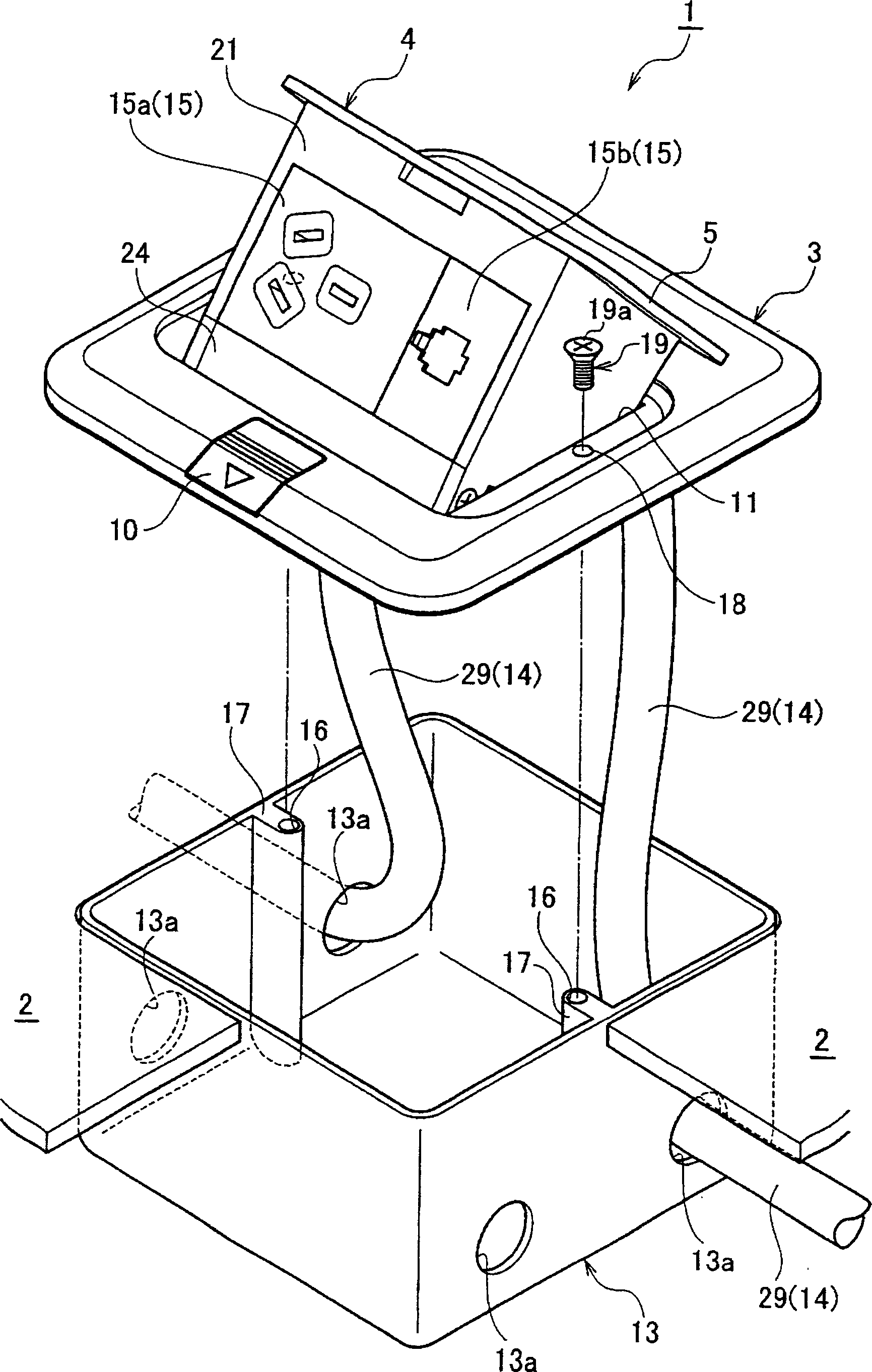
[0023] Hereinafter, embodiments of the present invention will be described with reference to the drawings. figure 1 It is a perspective view which shows the storage state of the storage movable body of the floor socket apparatus concerning embodiment of this invention. figure 2 It is a side view showing the protruding state of the protruding movable body of the ground socket device according to the embodiment of the present invention. image 3 It is an exploded perspective view of the ground socket device of embodiment of this invention. Figure 4 It is an exploded perspective view of the movable body of the ground socket device according to the embodiment of the present invention viewed from the back side. Figure 5 It is a perspective view which looked at the floor socket apparatus which concerns on embodiment of this invention from the underfloor side. also, Figure 6 It is a rear view of the ground socket device of embodiment of this invention. In addition, in this sp...


PUM


Abstract

The present invention provides a ground socket device capable of switching between a protruding state of a movable body (4) having a connector module (15) protruding above the floor and a storage of the movable body (4) under the floor In the pop-up type ground socket device (1) in the state, since the connector module (15) is inserted into the frame portion 21 of the movable body (4) from below, it is pushed into the frame portion 21 from below by the fixing member (24). the connector module (15), so when the underfloor wiring is connected to the connector module (15), the underfloor wiring can be connected to the connector module ( 15) on. Therefore, such a ground socket device can simplify the underfloor wiring and the connection work of the connector modules.

Description

technical field [0001] The present invention relates to a pop-up type floor socket device installed on the floor. Background technique [0002] Conventional socket devices of this type are configured in such a way that a protruding state in which a movable body having a socket protrudes from the opening of the cover plate to the floor, and a storage state in which the movable body is stored under the floor (for example, patent Literature 1). [0003] In the ground socket device disclosed in Patent Document 1, the movable body has a structure in which the socket (in Patent Document 1, the socket body) is sandwiched between the upper cover and the lower cover. Then, by rotatably installing the lower cover on the cover plate (attachment plate in Patent Document 1) via the shaft, the movable body can be switched between the protruding state and the housed state. [0004] This kind of floor socket device is constructed in the order of fixing the cover plate so as to close the u...

Claims


Application Information

Patent Timeline
IPC IPC(8): H02G3/18H01R13/46H01R13/73
Inventor 松冈秀树
Owner MATSUSHITA ELECTRIC WORKS LTD
Why Eureka
Try Eureka