Construction of coupling exhaust pipes of vehicle

A technology for connecting structures and exhaust pipes, applied in the directions of exhaust devices, mufflers, engine components, etc., can solve the problems of increased weight and cost, large number of parts, troublesome welding process, etc., to avoid weight and easy to manufacture. , the effect of reducing the number of

Active Publication Date: 2006-08-02
NAKAGAWA SANGYO
View PDF1 Cites 2 Cited by
  • Summary
  • Abstract
  • Description
  • Claims
  • Application Information

AI Technical Summary

Problems solved by technology

[0005] However, the structure of the above-mentioned prior art needs to fix the connection flanges 61, 62 or the snap rings 71, 72 on the pipe end outer peripheries of the exhaust pipes 1, 2 by welding, so not only the stress concentrates on the weld joint but also the There is a problem that it is easy to break due to the vibration of the vehicle, and there is also a problem that the welding process is troublesome.
Furthermore, in the first prior art example, if the surface pressure is raised in order to prevent the gasket 63 from leaking gas, it is necessary to make the connection flanges 61, 62 thicker by 10 to 12 mm, which increases the weight and cost. problem, and in the second prior art example, there is a problem of a large number of parts

Method used


Image

  • Construction of coupling exhaust pipes of vehicle
  • Construction of coupling exhaust pipes of vehicle
  • Construction of coupling exhaust pipes of vehicle

Examples


Embodiment Construction

[0026] (first embodiment)

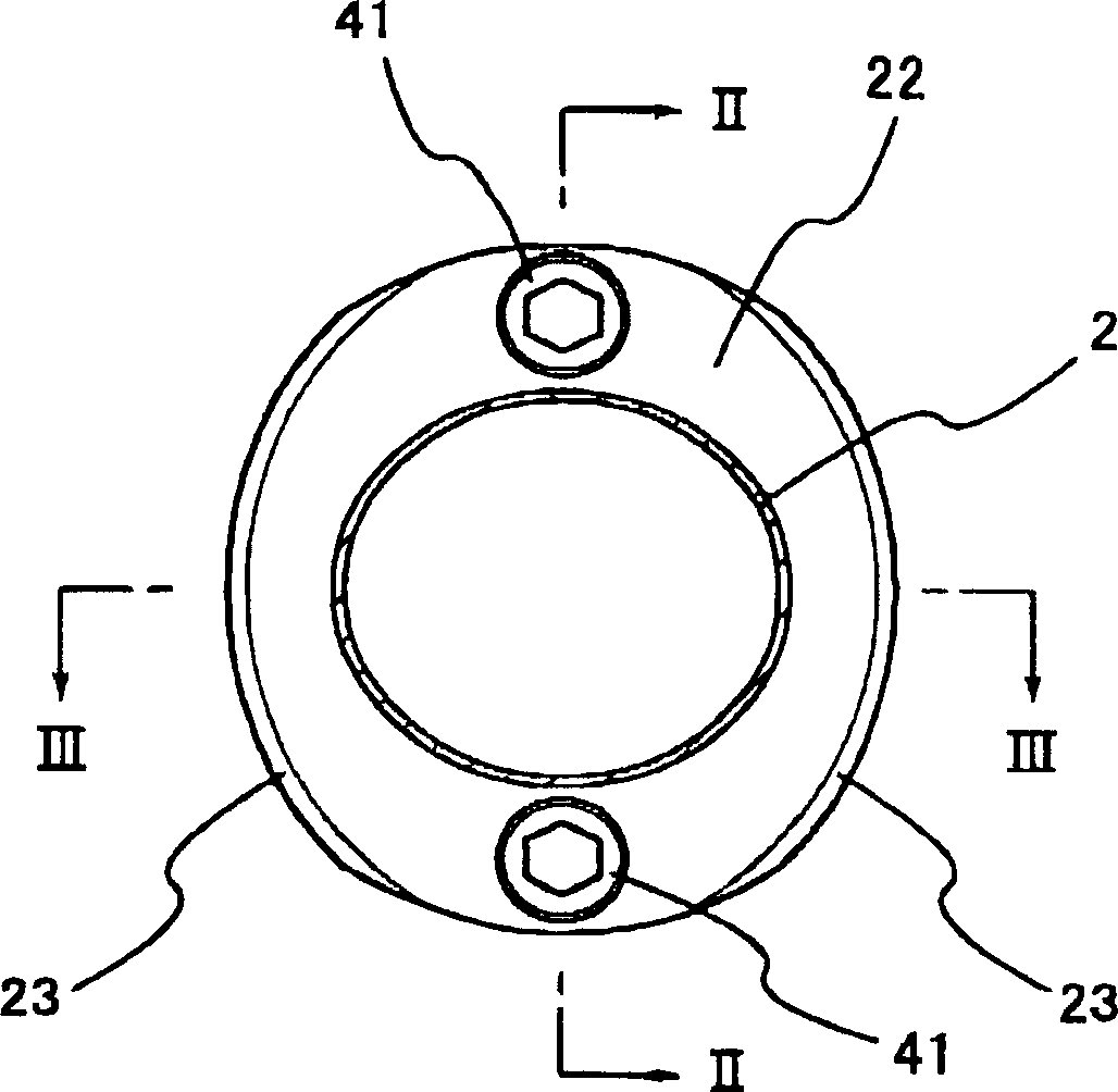
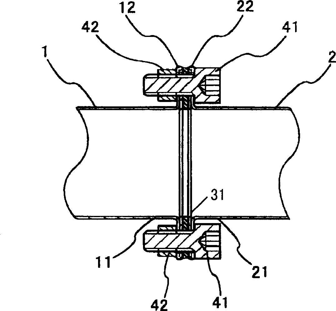
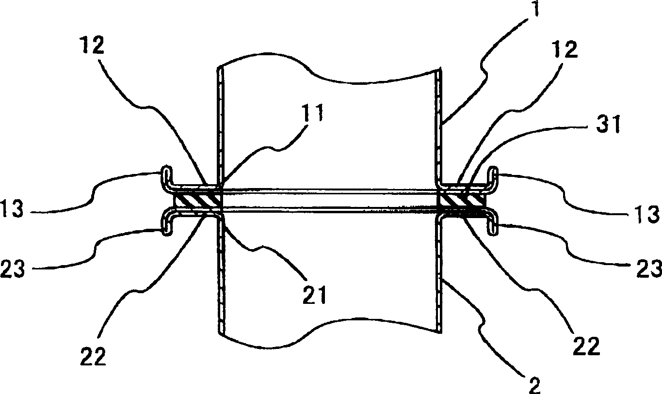
[0027] Figure 1 ~ Figure 3 An example of the connection structure of the present invention is shown. figure 1 is a cross-sectional view of a connected vehicle exhaust pipe, figure 2 , image 3 respectively along figure 1 The longitudinal sectional view of line II-II and line III-III. exist figure 2 , image 3 Among them, the upstream side exhaust pipe 1 and the downstream side exhaust pipe 2 are located at positions where the opening edges 11 and 21 face each other. The wall thickness of each exhaust pipe 1, 2 is, for example, 1.2 to 1.5 mm, and its opening edges 11, 21 are bent outward in the radial direction by expanding and forming, and then folded inward in the radial direction to form a protrusion with a predetermined width around the opening. Edge 12,22. The flange portions 12, 22 are provided with a gasket 31 therebetween, butted against each other, at positions symmetrical in the radial direction ( figure 1 ) are combined with...


PUM


Abstract

The present invention provides an opening edge of an upstream-side exhaust pipe and an opening edge of a downstream-side exhaust pipe opposed to the opening edge of the upstream-side exhaust pipe are bent radially outward and thereafter radially inward by molding to form a circumference of the upstream-side exhaust pipe and a circumference of the downstream-side exhaust pipe as a flange portion respectively. After both flange portions are butted to each other through a gasket disposed therebetween, they are mechanically coupled to each other with a bolt and a nut.

Description

technical field [0001] The present invention relates to a connection structure of vehicle exhaust pipes, and particularly relates to a connection structure capable of connecting exhaust pipes to each other with a small number of components without welding. Background technique [0002] Figure 11 , FIG. 12 shows an example of a conventional exhaust pipe connection structure. In FIG. 12 , a substantially diamond-shaped ( Figure 11 ) connecting flanges 61, 62, by using bolts 64 and nuts 65 to connect the connecting flanges 61, 62 through the gasket 63, the two exhaust pipes 1, 2 are thus connected together (the first prior art example). [0003] Figure 13 , FIG. 14 shows another example of the conventional exhaust pipe connection structure. In FIG. 14 , snap rings 71 and 72 formed in a U-shaped cross-section are welded to the outer peripheries of the pipe ends of the upstream exhaust pipe 1 and the downstream exhaust pipe 2 respectively. A ring-shaped liner 73 is inserte...

Claims


Application Information

Patent Timeline
IPC IPC(8): F01N7/18F01N13/18F01N13/08
Inventor 中川幸弘
Owner NAKAGAWA SANGYO
Why Eureka
Try Eureka