Supercharge Your Innovation With Domain-Expert AI Agents!

Ventilating device with temperature-humidity dual exchange

A ventilation device, temperature and humidity technology, applied in space heating and ventilation, space heating and ventilation details, home appliances, etc., can solve the problems of heat exchange efficiency that needs to be improved, flow field chaos, and unfavorable exchange efficiency, etc., to achieve improvement Temperature and humidity exchange efficiency, sensible heat exchange efficiency increase, and the effect of solving indoor air pollution

Inactive Publication Date: 2006-08-09
FU ZHUN PRECISION IND SHENZHEN +1
View PDF0 Cites 7 Cited by
  • Summary
  • Abstract
  • Description
  • Claims
  • Application Information

AI Technical Summary

Problems solved by technology

[0007] (1) The flow field of the air entering the total heat exchange runner is chaotic and the flow distribution is uneven
As we all know, the maximum exchange efficiency can be achieved when the two airflows of the intake air and the exhaust air evenly flow through the runner in counter flow mode to exchange sensible heat and latent heat. The wind direction of the tiny channel in the runner is at a vertical angle, and the end of the flow path of the main airflow blown in is a facing end plate of the casing, which is subjected to the interaction between the secondary airflow directly impacting the end plate and the incoming main airflow and The steering effect makes the flow field in between very chaotic, resulting in the uneven distribution of the air volume entering the runner. The above-mentioned uneven air volume distribution and the chaotic phenomenon of the flow field make it difficult for the exhaust and intake air to flow through in a countercurrent manner. The runner is very detrimental to the overall exchange efficiency
[0008] (2) Heat exchange efficiency needs to be improved
Since the exchange of sensible heat and latent heat is achieved by passing the two airflows through the runner with a honeycomb structure during the intake and exhaust, the heat exchange efficiency is completely determined by the runner, but the runner is made of a material with strong hygroscopicity and strong permeability. Material is the main appeal, and the improvement of heat transfer effect is often unable to take into account. There is still a lot of room for improvement in the efficiency of sensible heat exchange.

Method used


Image

  • Ventilating device with temperature-humidity dual exchange
  • Ventilating device with temperature-humidity dual exchange
  • Ventilating device with temperature-humidity dual exchange

Examples


Embodiment Construction

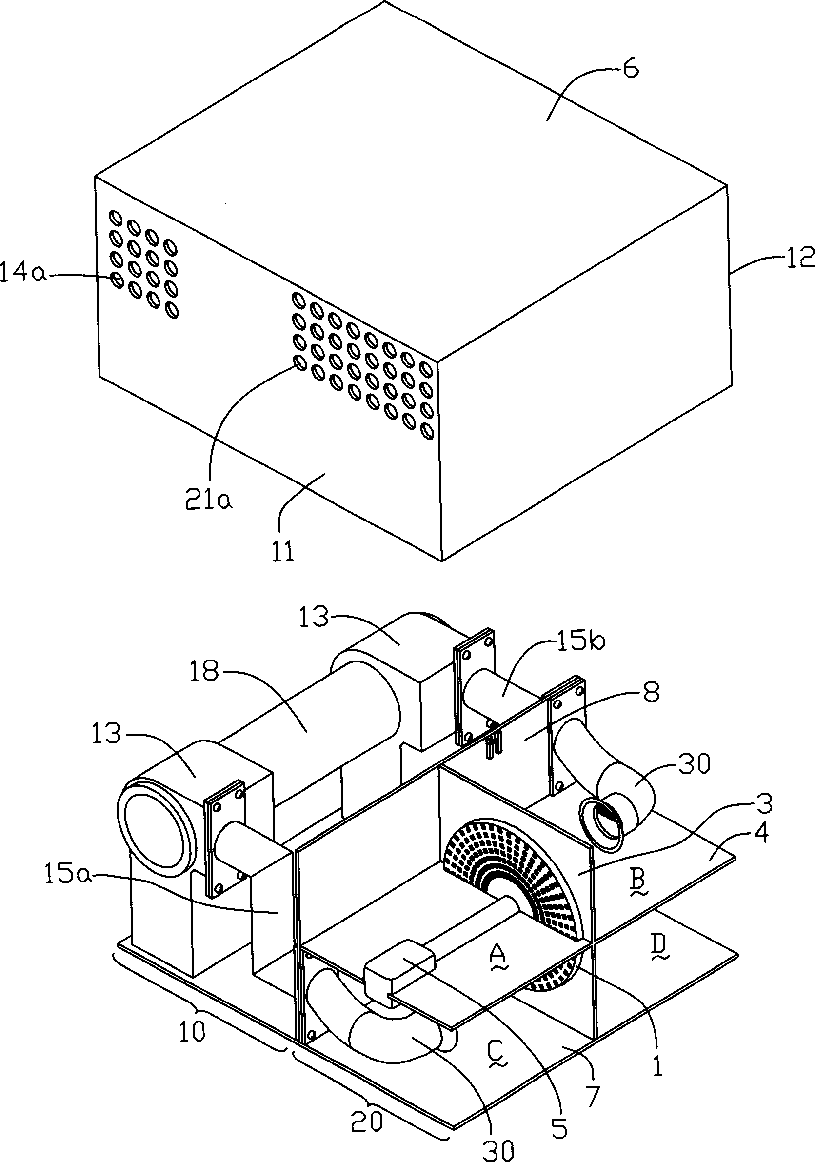
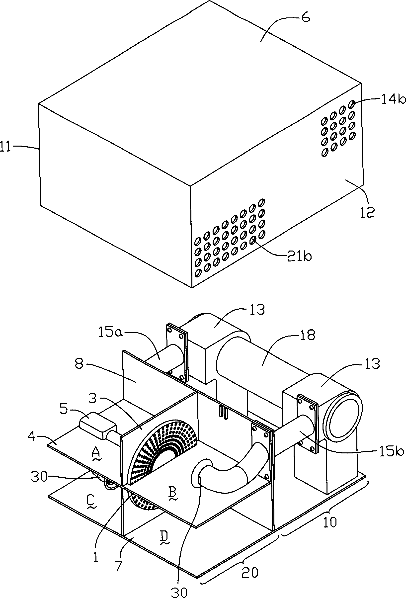
[0027] figure 2 and image 3 It is a three-dimensional schematic diagram of the first embodiment of the ventilation device with double exchange of temperature and humidity in the present invention. It is basically composed of a fan chamber 10 and a total heat exchange chamber 20. The two chambers are formed by the combination of the upper cover 6 and the bottom plate 7. The inside of the casing is formed by separating the partition board 8 , and shares an indoor side wall 11 and an outdoor side wall 12 of the upper cover 6 .

[0028] The fan chamber 10 is provided with two fans 13 placed symmetrically, and the wall surfaces 11 and 12 corresponding to the upper cover 6 of the casing are respectively provided with relative exhaust inlets 14a and air inlets 14b. The motor 18 of rotating shaft is driven. The fan chamber 10 and the total heat exchange chamber 20 are provided with a partition 8 adjacent to each other, and the fans 13 are respectively connected to the partition 8 ...


PUM


Abstract

Present invention discloses a humiture double exchange ventilating device for improving indoor air quality and humiture switching performance. It contains at least a blower fan providing interblend two airflow, a rotating wheel having close-set miniature air duct distributed in not communicant air outlet and air inlet zone and respectively corresponding with above-mentioned two airflow, above-mentioned two airflow capable of proceeding temperature and humidity exchange through rotating wheel miniature air duct, at least a airflow guiding rectifying device setting on above-mentioned two airflow air duct, said invention solving indoor air pollution and humiture exchange efficiency.

Description

【Technical field】 [0001] The present invention relates to a ventilation device, in particular to a ventilation device for improving indoor and outdoor air quality and having double exchange of temperature and humidity. 【Background technique】 [0002] In actual daily life, in order to ensure the indoor air quality, it is often necessary to install ventilation devices such as air conditioners, especially in places where people are relatively concentrated, so that indoor pollutants and dirty air (exhaust) can be discharged outdoors in a timely manner. At the same time, the outdoor fresh air (air intake) is supplemented indoors to meet the needs of human health standards. [0003] However, directly replacing the indoor and outdoor air will cause a large amount of energy loss. For example, in summer, when a large amount of hot air with a high outdoor temperature is used to replace the cold air in the room that has been air-conditioned, a large energy loss will occur; On the othe...

Claims


Application Information

Patent Timeline
Patent Type & Authority Applications(China)
IPC IPC(8): F24F3/147F24F13/26
Inventor 刘泰健詹顺渊梁尚智范智峰
Owner FU ZHUN PRECISION IND SHENZHEN
Features
  • R&D
  • Intellectual Property
  • Life Sciences
  • Materials
  • Tech Scout
  • Unparalleled Data Quality
  • Higher Quality Content
  • 60% Fewer Hallucinations
Learn More