
Radiator of printed circuit board

A heat dissipation device and circuit board technology, which is applied in the fields of electrical digital data processing, cooling/ventilation/heating transformation, instruments, etc., can solve the problems of increased cost, long distance between the water tank body and the heating chip, and the fact that the water-cooled heat dissipation device cannot meet the requirements of actual use. Need to wait for the problem to achieve the effect of reducing the assembly space

Inactive Publication Date: 2006-08-16
THERMALTAKE
View PDF0 Cites 0 Cited by
  • Summary
  • Abstract
  • Description
  • Claims
  • Application Information

AI Technical Summary

Problems solved by technology

[0003] Although the above-mentioned existing heat dissipation device can cooperate with the tube body to cool down the heat-generating chip through the heat-dissipating fin group, the effect of heat dissipation can be achieved; The heat sink is connected, so the distance between the water tank body and the heating chip is relatively long, and the pipeline composed of the required pipe body is also relatively long, which not only takes up more space inside the casing, but also causes an increase in cost and the water tank itself. The assembly of the water tank is also more complicated; moreover, when the main computer needs to be repaired or replaced and the casing needs to be removed, it must be removed together with the water tank body and the pipe body, resulting in difficulty in disassembly and easy to cause damage to the original integrity. The main body and pipe body of the water tank were damaged due to careless disassembly; therefore, the existing general water-cooled heat sink cannot meet the needs of actual use

Method used


Image

  • Radiator of printed circuit board
  • Radiator of printed circuit board
  • Radiator of printed circuit board

Examples


Embodiment Construction

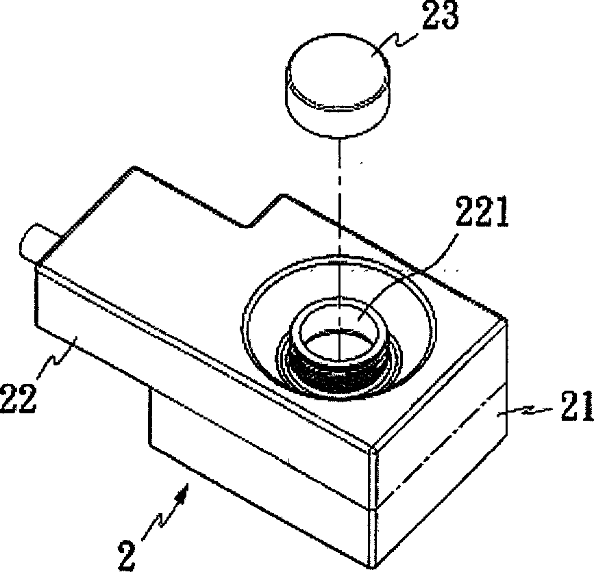
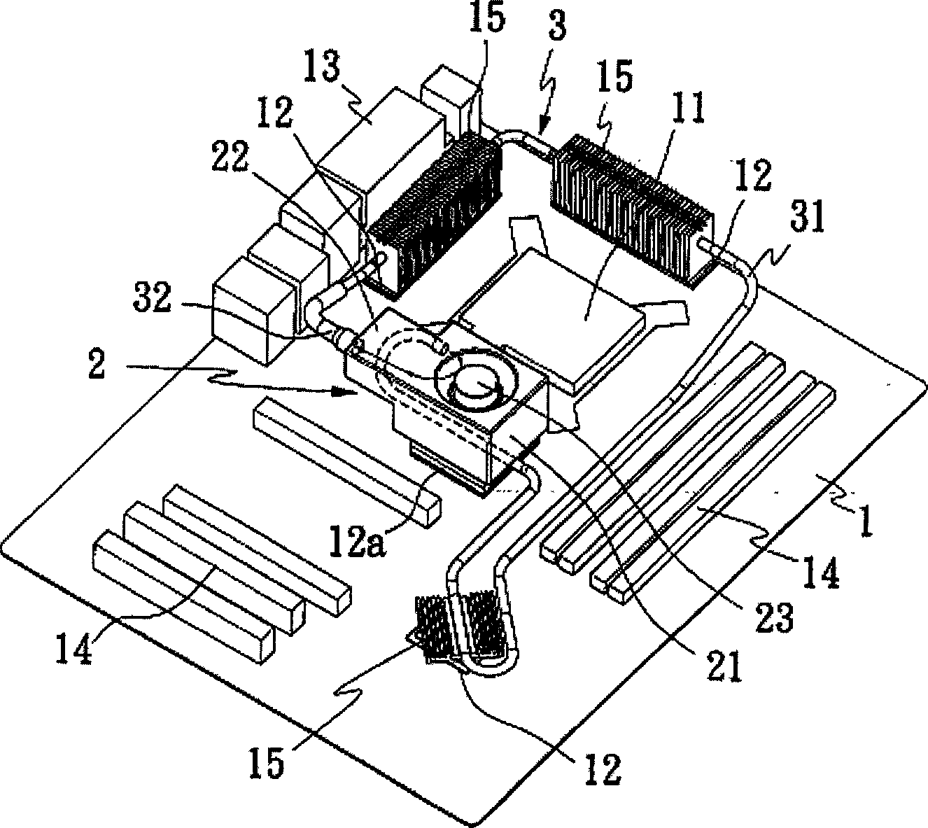
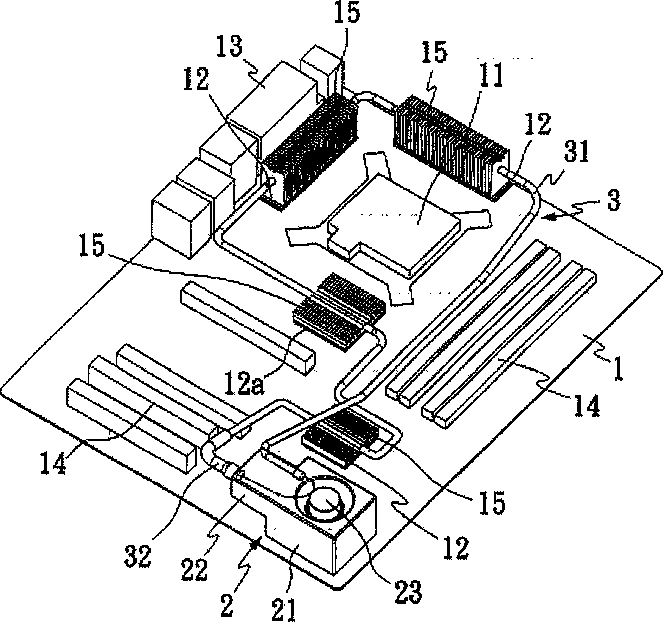
[0023] See attached figure 1 , 2 As shown, the present invention mainly includes a circuit board 1, a circulation mechanism 2 and a flow guide unit 3. The circulation mechanism 2 is arranged at an appropriate place on the circuit board 1, and the flow guide unit 3 is connected to the heat source on the circuit board 1 and communicates with the circulation. The mechanism 2 can reduce the assembly space required by the circulation mechanism 2 and the flow guide unit 3 when the circuit board 1 is arranged in the casing, and the circulation mechanism 2 and the flow guidance unit 3 will not be affected when the casing is disassembled or replaced setting.

[0024] The aforementioned circuit board 1 is provided with a central processing unit 11 , several electronic chips 12 , several connectors 13 and slots 14 , and the electronic chips 12 , 12 a are respectively provided with heat sink groups 15 .

[0025] The circulation mechanism 2 is composed of a brake unit 21 and a storage un...


PUM


Abstract

A heat radiation device of circuit board is composed of circulation mechanism set on proper position of circuit board as well as flow guiding unit connected to heating source on circuit board and connected to said circulation mechanism .The said device can be widely used in heat radiation system of various circuit boards.

Description

Technical field: [0001] The invention relates to the technical field of equipment heat dissipation, in particular to a heat dissipation device for a circuit board. technical background: [0002] At present, the water-cooled heat dissipation device used by the circuit board of the general computer mainframe includes a water tank body arranged on the inner surface of the mainframe casing, the water tank body is connected with a pump, and the water tank body is connected with a pipe body, the pipe body It is connected to the heat sink group of the heating chip on the circuit board; the heat source of the heating chip can be transmitted to the heat sink group, and at the same time, the pump can output the water in the water tank body through the tube body, and cool down the heat sink group through the tube body. In order to achieve the effect of heat dissipation. [0003] Although the above-mentioned existing heat dissipation device can cooperate with the tube body to cool down...

Claims


Application Information

Patent Timeline
Patent Type & Authority Applications(China)
IPC IPC(8): G06F1/20H05K7/20
Inventor 林培熙
Owner THERMALTAKE
Learn More