

Sefety apparatus of passenger conveying equipment
A technology of passenger conveying equipment and safety device, applied in the field of passenger conveying equipment, can solve the problems of increased cost, detection of obstacles to the circulation driving of passenger conveying equipment, damage to collision sensors, etc., to achieve the effect of improving safety
- Summary
- Abstract
- Description
- Claims
- Application Information
AI Technical Summary
Problems solved by technology
Method used
Image

Examples
Embodiment Construction
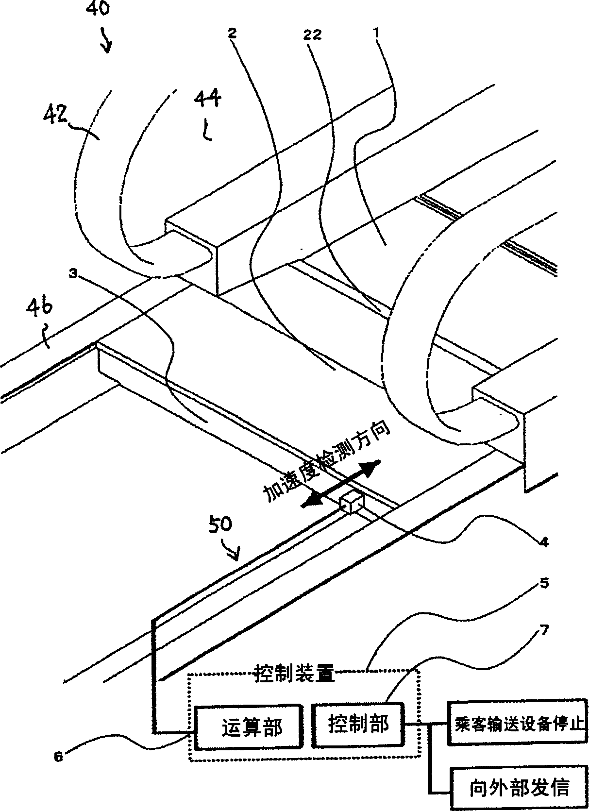
[0015] Next, an embodiment of the safety device of the passenger conveying facility according to the present invention will be described with reference to the drawings. figure 1 The lower end of the passenger conveyor 40 is shown in perspective. Below between railings 44 formed together with the left and right handrails 42, the steps 1 connected in a ring shape are arranged. A plurality of parallel grooves and protruding comb-shaped teeth 22 are formed on the upper surface and the arc surface on the front side of the pedal 1 . The entrance and exit floor 2 is arranged so as to be horizontally overlapped with a part of the footboard 1 . A plurality of parallel grooves and protruding comb-shaped teeth 22 are also formed on the upper surface of the access floor 2 . The entrance / exit floor 2 is stationary, and a main frame body 46 is arranged on the end in the width direction. An entrance and exit floor support beam 3 is also arranged, and the entrance and exit floor support be...
PUM
 Abstract
Description
Claims
Application Information