Winding state indicator mechanism for a mechanical timepiece

A technology for clock components and indicating mechanisms, which is applied to the driving mechanism of clocks, mechanically driven clocks, and ratchet mechanisms of mainsprings, etc., can solve the problems of disturbing the vibration amplitude of the pendulum, the difficulty of the drum wheel, and disturbing the normal operation of the clock gears.

Inactive Publication Date: 2006-08-23
ETERNA SA FAB D HORLOGERIE
View PDF0 Cites 7 Cited by
  • Summary
  • Abstract
  • Description
  • Claims
  • Application Information

AI Technical Summary

Problems solved by technology

In fact, it is possible that the only one drum has difficulty, which disturbs the vibration amplitude of the pendulum and, therefore, disturbs the normal working of the clock gear.

Method used


Image

  • Winding state indicator mechanism for a mechanical timepiece
  • Winding state indicator mechanism for a mechanical timepiece
  • Winding state indicator mechanism for a mechanical timepiece

Examples


Embodiment Construction

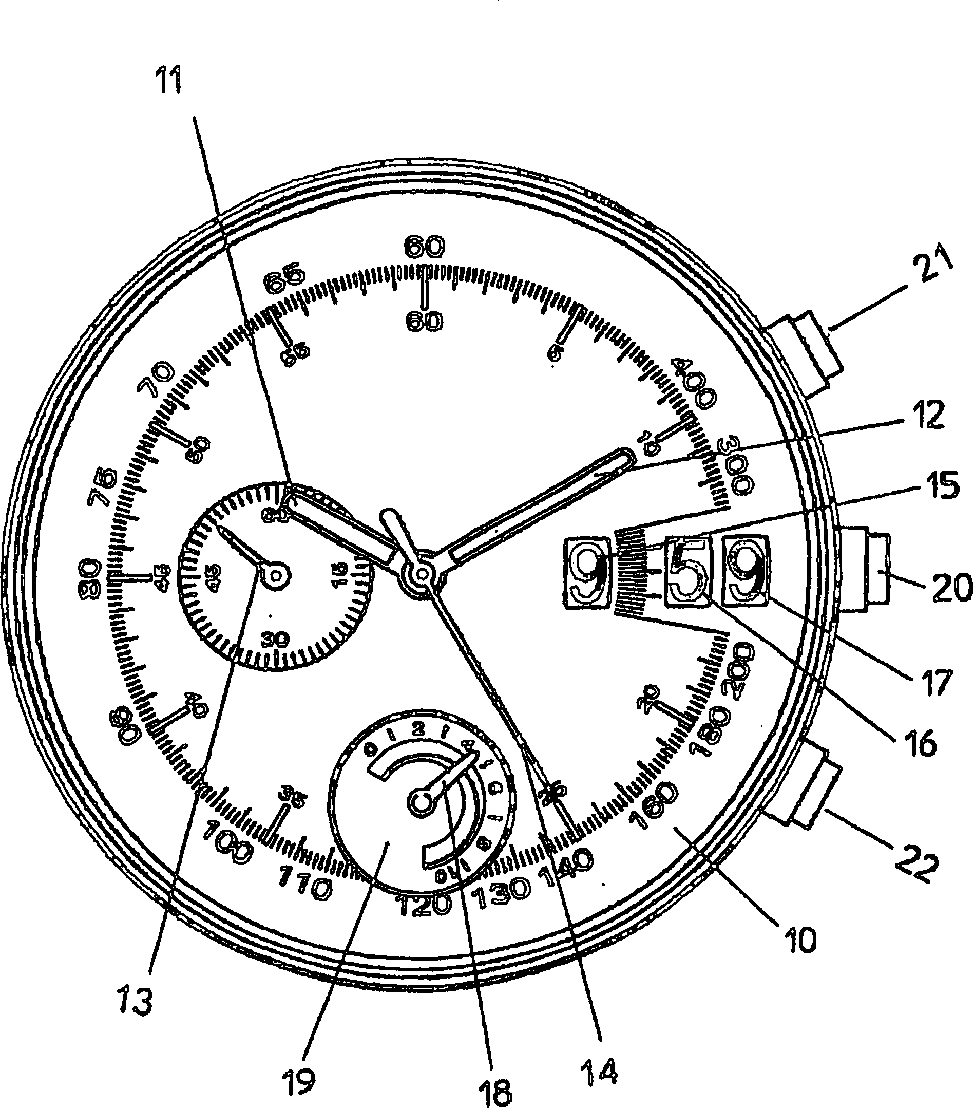
[0022] [twenty two] figure 1 The chronograph shown schematically shows the current hour, minute and second on a dial 10 in a conventional manner by means of two central hands 11 and 12 and a small hand 13 at 9 hours.

[0023] [23] The clock also uses a central pointer 14 to display the seconds of the time measurement, and the indications of the hour, the tens of the minute, and the ones of the minute are provided by three wheels 15, 16 and 17, respectively. These three roulettes are exposed behind the observation hole installed in the dial 10.

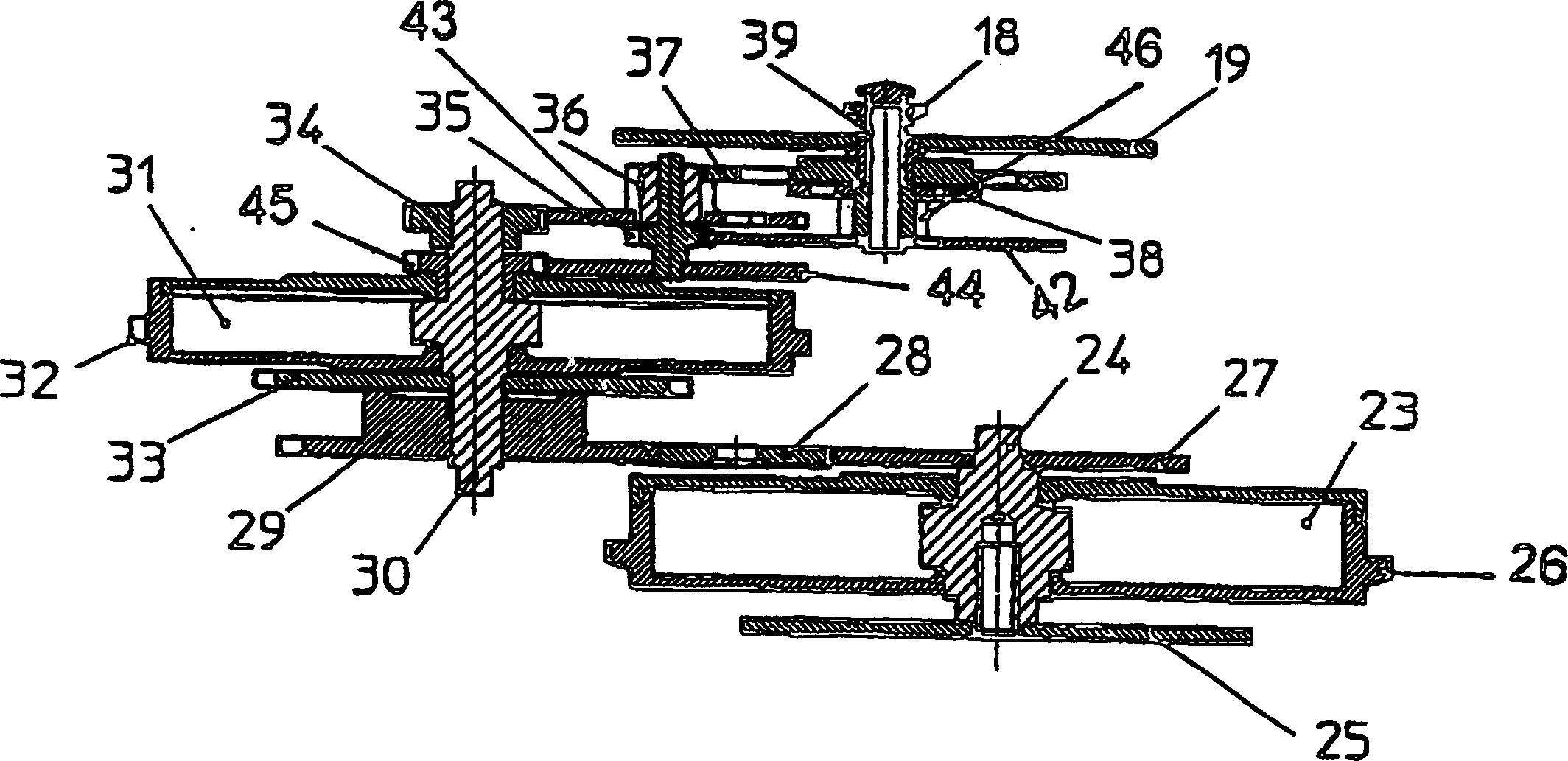
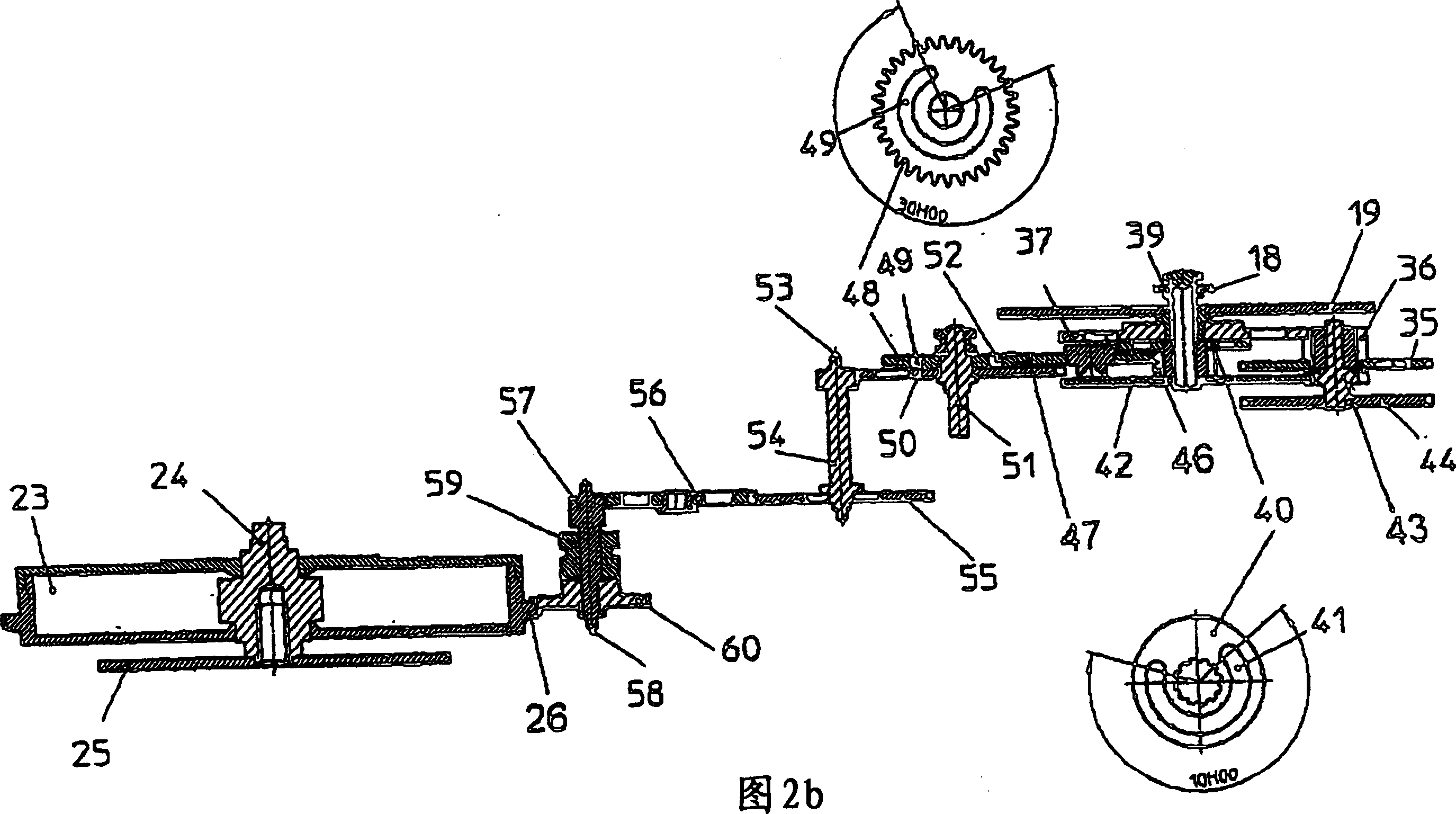
[0024] [24] Finally, a small pointer 18 and a rotating small dial 19 are set at 6 hours to display the operating reserve time of the component, which will be described in conjunction with FIG. 2.

[0025] [25] The movement device of the timepiece has a chronograph type mechanical gauge (calibre) as the main component, such as the gauge with reference number 7750 commercialized by ETA SA (Switzerland). The gauge is combined into an auxilia...


PUM


Abstract

The invention relates to a running reserve indicator for a mechanical clockwork provided with a main barrel for actuating a going train and at least one second barrel for actuating a mechanism allocated to an auxiliary function which is carried out during a definite period of time. The running reserve displayed with the aid of a hand and a dial is always equal to the running reserve of the barrel having the smallest reserve.

Description

Technical field [0001] [01] The present invention relates to a movement device of a mechanical timepiece, the energy of which is provided by a spring housed in a drum. Specifically, the present invention relates to an indicating mechanism for the reserve de marche of the movement device of a mechanical timepiece. The timepiece is equipped with a main drum for driving a precision gear train and at least one for driving a pair of The auxiliary drum is provided with gears with auxiliary functions, and the auxiliary functions should be performed within a minimum certain time. Background technique [0002] [02] This kind of mechanism is mainly used for the movement device of a chronograph mechanical timepiece, which uses a disc (disque) to display the hours and minutes of the time measurement. In this case, the minimum determination time is equal to the maximum measurable time. [0003] [03] It has been known that this kind of display is stronger than the pointer display. It can provi...

Claims


Application Information

Patent Timeline
Patent Type & Authority Applications(China)
IPC IPC(8): G04B1/12G04B9/02G04F7/08
CPCG04B1/12G04F7/08G04B9/02G04F7/089G04F7/0895G04B9/005
Inventor P·格贝尔W·迈尔
Owner ETERNA SA FAB D HORLOGERIE
Why Eureka
Try Eureka