Encoding method and device

A coding method and coding technology, applied in the field of coding, can solve problems such as lossy processing

Inactive Publication Date: 2006-08-23
KONINK PHILIPS ELECTRONICS NV
View PDF2 Cites 2 Cited by
  • Summary
  • Abstract
  • Description
  • Claims
  • Application Information

AI Technical Summary

Problems solved by technology

In such encoders, the quantization process is a lossy process that results in blocking artifacts

Method used


Image

  • Encoding method and device
  • Encoding method and device

Examples


Embodiment Construction

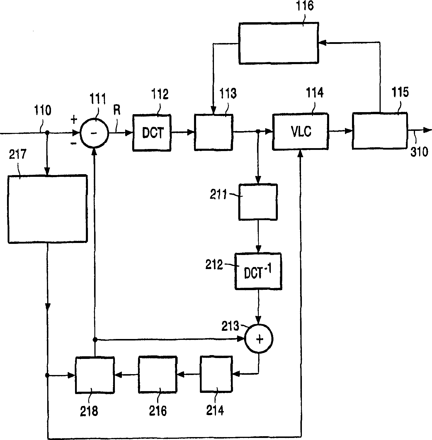
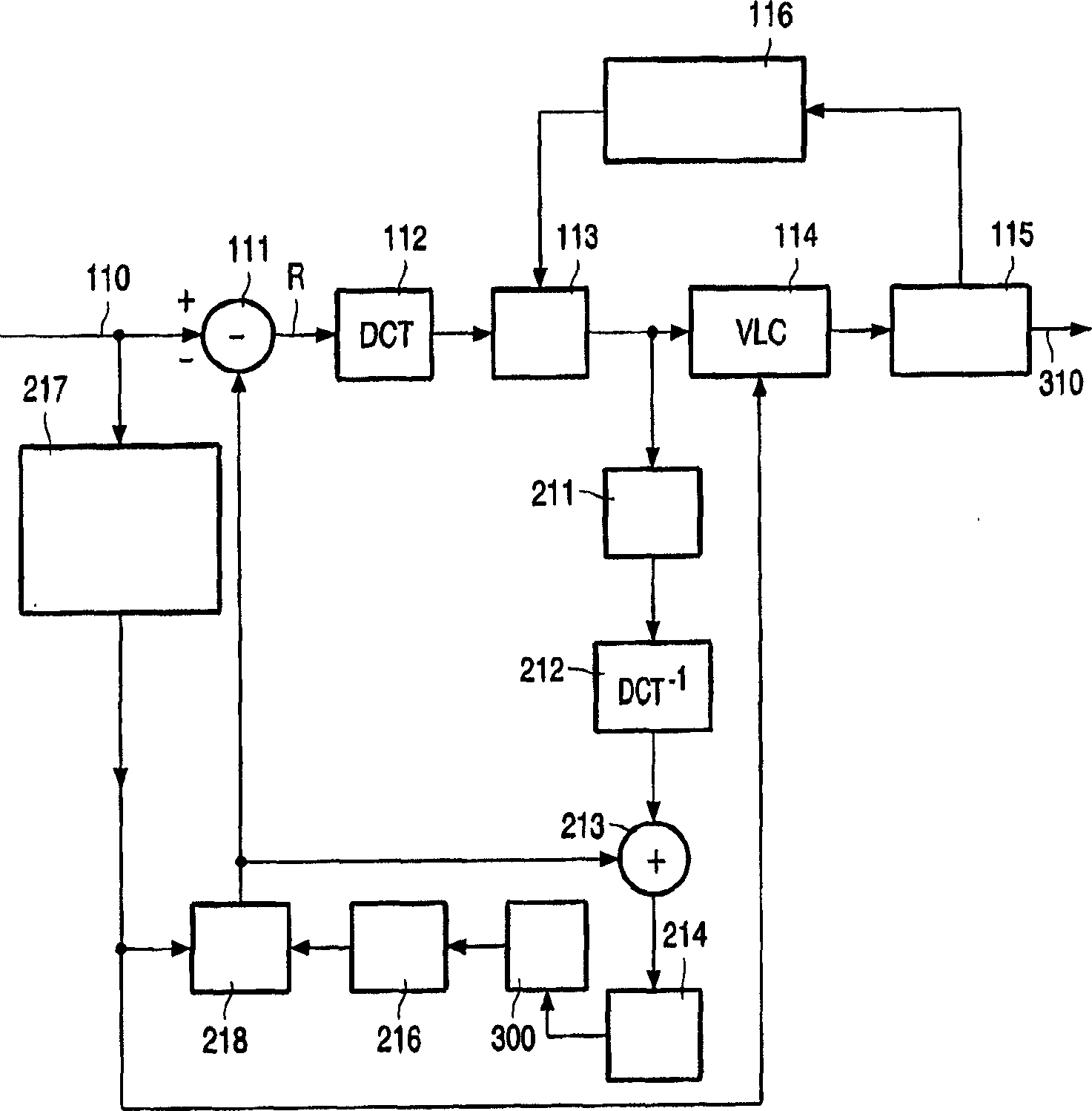
[0015] figure 1 A block diagram of a conventional encoding device is given. Such devices typically include an encoding branch and a prediction branch. The encoding branch comprises a subtractor 111, a DCT circuit 112, a quantization circuit 113, an entropy encoder (e.g., a VLC circuit 114), a buffer 115, and a rate control circuit 116 connected in series, wherein the input of the encoding branch receives an input coded sequence 110, the input The coded sequence 110 is subdivided into subframes. The prediction branch comprises an inverse quantization circuit 211 , an inverse DCT circuit 212 , an adder 213 , a frame memory circuit 216 and a motion compensation circuit 218 connected in series between the output of the quantization circuit 113 and the negative input of the subtractor 111 . A deblocking filter (reference number 214 ) may be provided between the output of the adder 213 in the prediction branch and the input of the frame memory 216 . The prediction branch also com...


PUM


Abstract

The invention relates to an encoding method applied to an input video sequence comprising successive frames partitioned in subframes and comprising the steps of estimating a motion vector for each subframe, transforming, quantizing and coding a so-called input residual signal, generating a predicted frame, generating a motion-compensated predicted frame on the basis of said predicted frame and the motion vectors, and, by difference between the current frame and said motion-compensated predicted frame, generating said input residual signal. According to the invention, the encoding method is characterized in that the predicted frame generating step is followed by a temporal filtering sub-step carried out on the predicted frame, before the motion compensated predicted frame generating step.

Description

technical field [0001] The invention relates to a coding method applied to an input video sequence comprising consecutive frames divided into subframes, said method comprising at least the following steps: [0002] - estimating motion vectors for each subframe of the current frame to be coded; [0003] - transform, quantize and encode the so-called input residual signal; [0004] - generating a predicted frame based on the signal obtained after the quantization step, at least by an inverse quantization step, an inverse transformation step, an addition step, with a spatial filtering step or without a spatial filtering step; [0005] - generating a motion-compensated predicted frame based on said predicted frame and motion vectors respectively associated with a subframe; [0006] - generating said input residual signal by means of a difference between a current frame and said motion compensated predicted frame. [0007] The invention also relates to a device for carrying out ...

Claims


Application Information

Patent Timeline
Patent Type & Authority Applications(China)
IPC IPC(8): H04N7/26
CPCH04N19/00896H04N19/82H04N19/51
Inventor S·德尔科尔索
Owner KONINK PHILIPS ELECTRONICS NV
Why Eureka
Try Eureka