
Workpiece holder and workpiece transporting clamp

A technology of workpiece holder and workpiece, applied in the field of workpiece holder

Inactive Publication Date: 2010-11-03
TRINITY IND INC
View PDF2 Cites 0 Cited by
  • Summary
  • Abstract
  • Description
  • Claims
  • Application Information

AI Technical Summary

Problems solved by technology

[0013] Recently, however, there have been cases where a water flow is generated in a hydraulic transfer tank to move the workpiece from the downstream side to the upstream side while performing water flow. Pressure transfer, because the relative speed of the workpiece W during hydraulic transfer is accelerated, so the water flow resistance is also increased. In the experiment, the workpiece W fell off in the hydraulic transfer tank
[0014] Therefore, a workpiece holder using a thicker plate and increased spring strength (rigidity) was trial-manufactured as the flexible plate 55, but it was found that loading and unloading the workpiece to the jig 51 W becomes difficult without much change in gripper strength compared to
[0015] Also, since a thick leaf spring must be formed by bending many times, there is a problem that the manufacturing cost increases

Method used


Image

  • Workpiece holder and workpiece transporting clamp
  • Workpiece holder and workpiece transporting clamp
  • Workpiece holder and workpiece transporting clamp

Examples


Embodiment 1

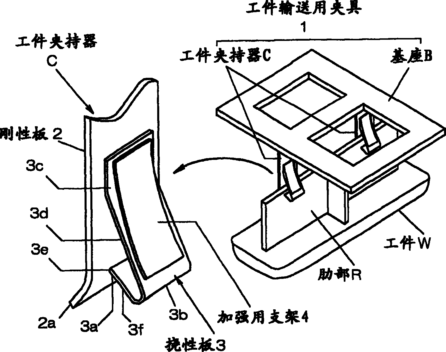
[0029] figure 1 The shown workpiece transport jig 1 holds the ribs R formed on the back side of the workpiece W and transports the workpiece W. Therefore, on the base B transported by a conveyor or a robot (not shown), the Clampers C for clamping the ribs R are attached at positions corresponding to the ribs R at predetermined intervals.

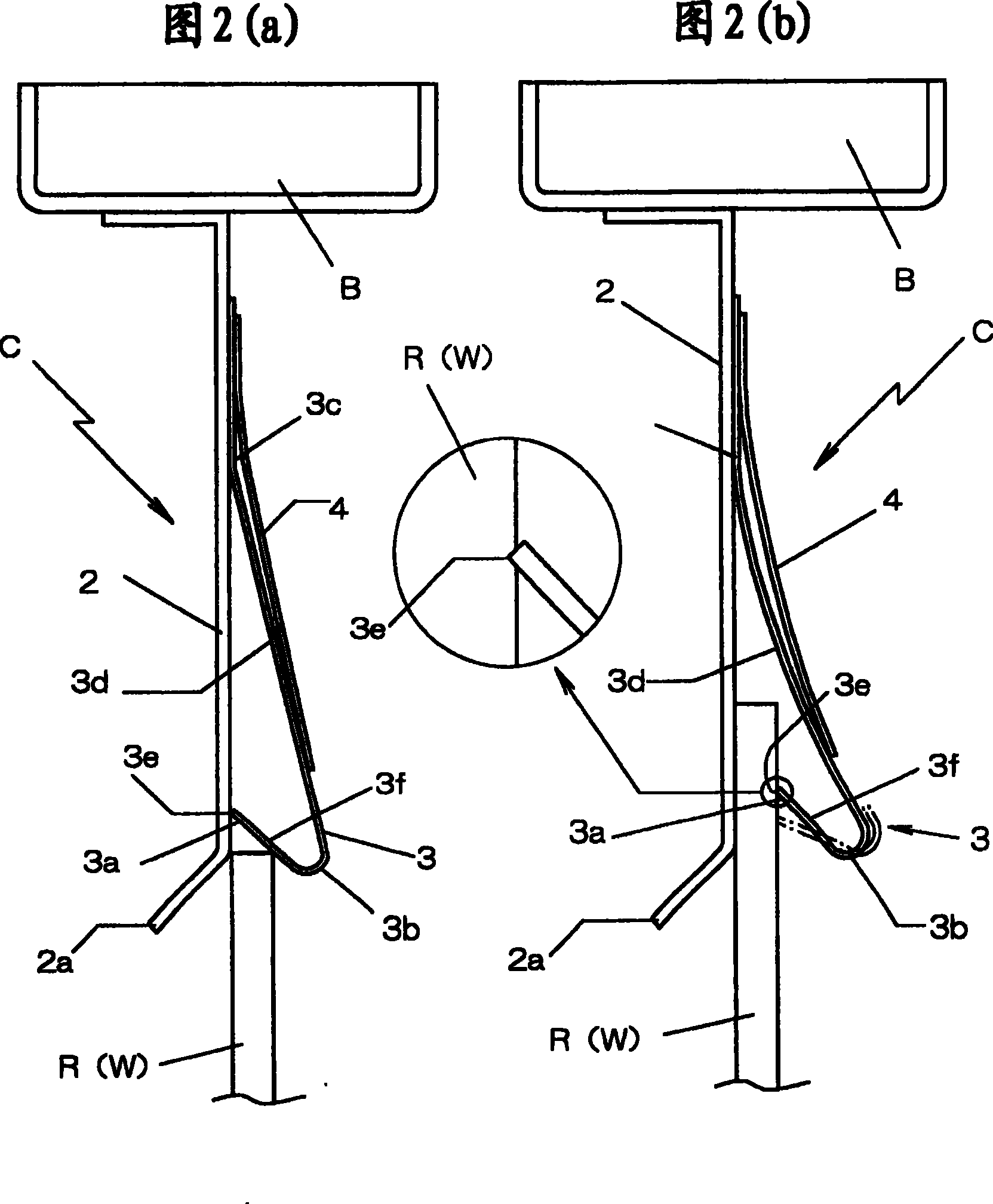
[0030] The workpiece holder C is formed such that one end side of the flexible plate 3 is overlapped and welded and fixed on the rigid plate 2, which is fixed on the base B, and is held by the elastic force of the flexible plate 3 from its free end. The 3a side inserts the workpiece W between the rigid plate 2 and the flexible plate 3 .

[0031] The rigid board 2 uses a metal material with higher bending rigidity (EI value) than the flexible board 3, and even if the same material is used, the rigidity can be increased by selecting a material with a larger thickness and width.

[0032] In addition, the size of the rigid plate 2 varies depe...


PUM


Abstract

The object of the invention is to facilitate fitting of a workpiece by a simple structure without largely increasing manufacturing cost, and prevent dropping of the workpiece even when external force is applied during conveyance. The work clamper 1, one end of a flexible plate 3 is overlapped with a rigid plate 2 and welded and fixed, and a workpiece W inserted from a free end 3a of the flexible plate 3 into a space between the rigid plate 2 and the flexible plate 3 is sandwiched by snapping force of the flexible plate 3. The free end 3a side of the flexible plate 3 is bent inwardly to make an acute angle, to form a hook-shaped cantilever of which portion from a tip 3b of the flexible plate 3 to the fixed end 3c side serves as a plate spring part 3d to energize the free end 3a to the rigid plate 2 side and of which portion from the tip 3b to the free end 3a serves as a turned part 3f for making a tip edge 3e of the flexible plate 3 bite into the workpiece W. To the rigid plate 2, a flat plate cantilever 4 for reinforcement to energize the plate spring part 3d from the top of the flexible plate 3 to the rigid plate 2 side is welded and fixed.

Description

technical field [0001] The present invention relates to a workpiece transfer jig for gripping a rib formed on the back side of a workpiece, conveying the workpiece, and a workpiece holder for fixing the workpiece thereon. Background technique [0002] Water pressure transfer printing is a surface decoration technology that transfers the printed pattern to the surface of the workpiece by immersing the workpiece in the water surface of a water-soluble film floating on the printed pattern, forming wood grain, leather, natural stone, etc. on the resin product. The pattern gives it a high-end feel. [0003] In this case, the workpiece is conveyed and submerged by a conveyor that moves on a hydraulic transfer tank or a robot that moves an arm on a prescribed track. However, since the workpiece cannot be directly fixed to the conveyor or the robot arm, it is fixed to a conveying jig, and the hydraulic transfer is performed while conveying the jig by a conveyor or robot. [0004] ...

Claims


Application Information

Patent Timeline
Patent Type & Authority Patents(China)
IPC IPC(8): B25B11/02
Inventor 山盛昌人逵本信也高须秀美
Owner TRINITY IND INC
Features
  • Generate Ideas
  • Intellectual Property
  • Life Sciences
  • Materials
  • Tech Scout
  • Unparalleled Data Quality
  • Higher Quality Content
  • 60% Fewer Hallucinations
Learn More