
Plasma display panel

A display panel, plasma technology, applied in the direction of alternating current plasma display panels, gas discharge electrodes, solid cathode components, etc., can solve the problems of PDP luminous efficiency, brightness reduction, energy waste, etc.

Inactive Publication Date: 2006-08-30
SAMSUNG SDI CO LTD
View PDF1 Cites 0 Cited by
  • Summary
  • Abstract
  • Description
  • Claims
  • Application Information

AI Technical Summary

Problems solved by technology

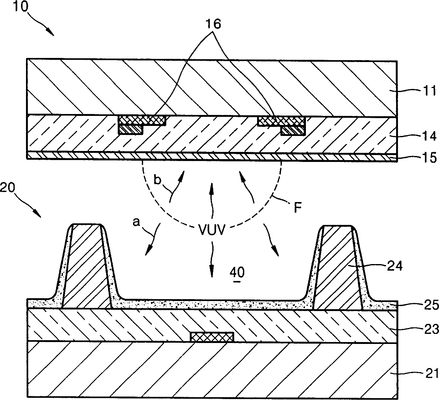
Since the generated VUV light is emitted through the top substrate 11, energy waste and reduction in PDP luminous efficiency and / or brightness may result.

Method used


Image

  • Plasma display panel
  • Plasma display panel
  • Plasma display panel

Examples


Embodiment Construction

[0025] Korean Patent Application No. 10-2005-0014084, filed on Feb. 21, 2005, in the Korean Intellectual Property Office, entitled "Plasma Display Panel," is hereby incorporated by reference in its entirety.

[0026] The present invention will be described more fully hereinafter with reference to the accompanying drawings, in which exemplary embodiments of the invention are shown. However, this invention may be embodied in different forms and should not be construed as limited to only the embodiments set forth herein. Rather, these embodiments are provided so that this disclosure will be thorough and complete, and will fully convey the scope of the invention to those skilled in the art. In the drawings, the dimensions of layers and regions are exaggerated for clarity of illustration. It will also be understood that when a layer is referred to as being "on" another layer or substrate, it can be directly on the other layer or substrate, or intervening layers may also be present...


PUM

PropertyMeasurementUnit
Thicknessaaaaaaaaaa

Abstract

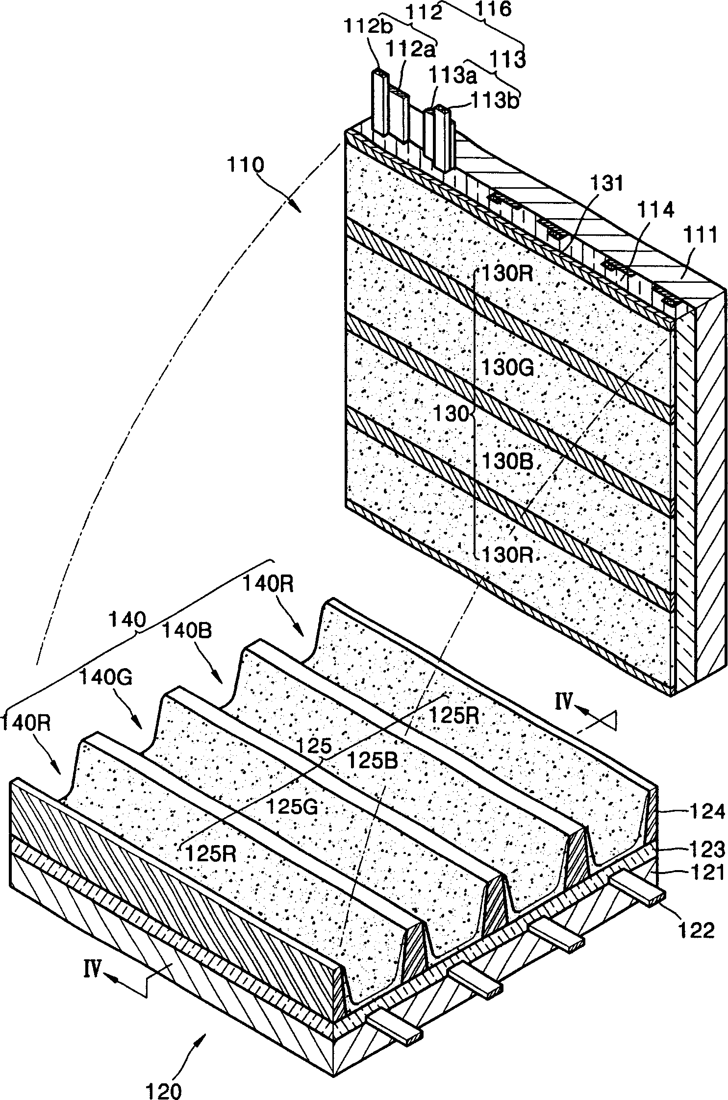
A plasma display panel (PDP) including a first substrate (111), a second substrate (121), a plurality of discharge cells (140) arranged between the first substrate (111), a plurality of electrodes (122), and a plurality of phosphor portions (130,125), the second substrate (121) arranged to at least partially overlap with the first substrate (111), the plurality of phosphor portions (130,125) including a first group of the plurality of phosphor portions (130) arranged on the first substrate (111), and a second group of phosphor portions (125) arranged on the second substrate (121).

Description

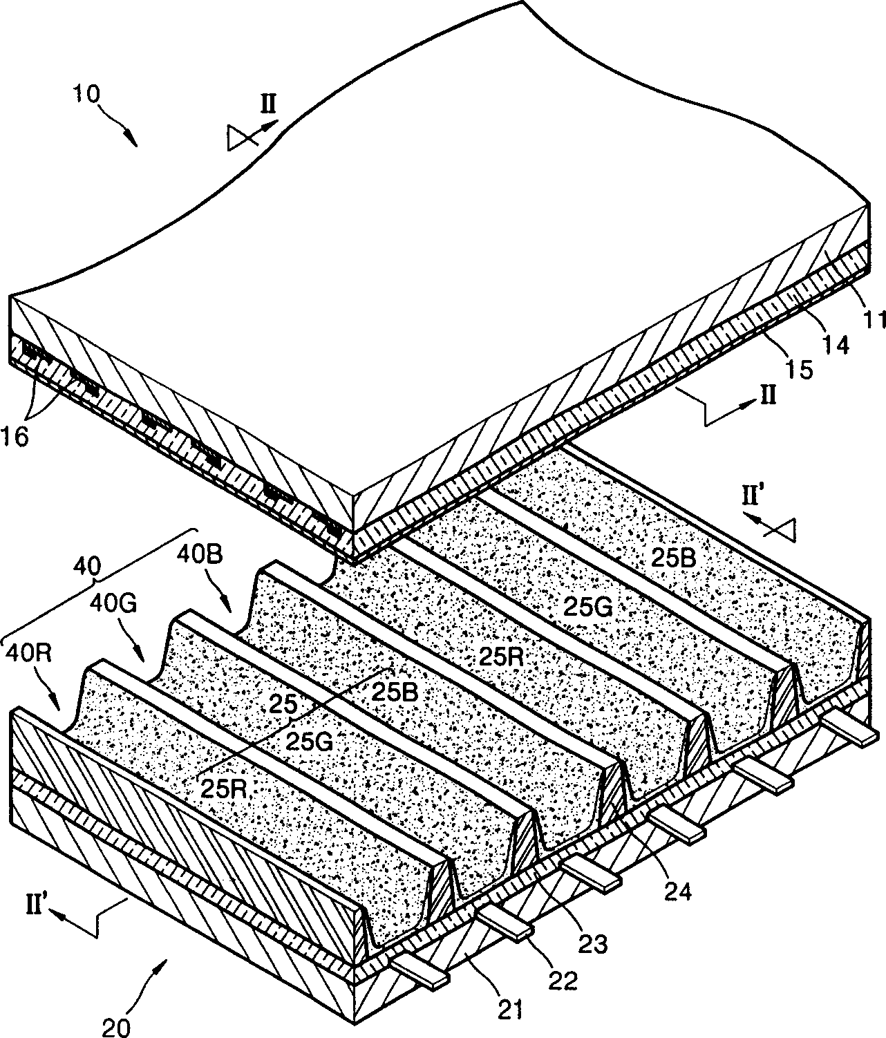
technical field [0001] The present invention relates to plasma display panels. More particularly, the present invention relates to a plasma display panel having improved brightness and / or improved efficiency, including improved luminous efficiency and / or improved power efficiency. Background technique [0002] 1 shows an exploded perspective view of a plasma display panel (PDP), and FIG. 2 shows a cross-sectional view of the plasma display panel along lines II-II and II'-II' of FIG. 1. Referring to FIG. [0003] The PDP includes a top panel 10 and a bottom panel 20 disposed opposite to the top panel 10 . The top panel 10 and the bottom panel 20 may have a top substrate 11 and a bottom substrate 21 , respectively. Pairs of discharge electrodes 16 may be arranged on the bottom surface of the top substrate 11 . The pair of discharge electrodes 16 may be covered by a top dielectric layer 14 and the top dielectric layer 14 may be covered by a passivation layer 15 . Address el...

Claims


Application Information

Patent Timeline
IPC IPC(8): H01J17/49H01J17/04H01J17/16H01J11/12H01J11/22H01J11/24H01J11/26H01J11/34H01J11/42
CPCH01J11/42H01J11/12A47J31/58A47J31/4403
Inventor 郑光珍
Owner SAMSUNG SDI CO LTD
Features
  • Generate Ideas
  • Intellectual Property
  • Life Sciences
  • Materials
  • Tech Scout
  • Unparalleled Data Quality
  • Higher Quality Content
  • 60% Fewer Hallucinations
Learn More