Electronic ballast, lighting device and method for operating high-pressure discharge lamps

A technology of high-pressure discharge lamps and electronic ballasts, which is applied in the direction of measuring current/voltage, the use of gas discharge lamps, energy-saving lighting, etc., to achieve the effect of uncomplicated evaluation and avoiding technical complexity

Inactive Publication Date: 2010-12-22
PATENT TREUHAND GESELLSCHAFT FUR ELECTRIC GLUEHLAMPEN MBH
View PDF6 Cites 0 Cited by
  • Summary
  • Abstract
  • Description
  • Claims
  • Application Information

AI Technical Summary

Problems solved by technology

In the case of this purely DC operation, interference phenomena which occur in the lamp due to asymmetry are avoided, but at the same time the higher frequencies of the interference are essentially isolated from the lamp

Method used


Image

  • Electronic ballast, lighting device and method for operating high-pressure discharge lamps
  • Electronic ballast, lighting device and method for operating high-pressure discharge lamps
  • Electronic ballast, lighting device and method for operating high-pressure discharge lamps

Examples


Embodiment Construction

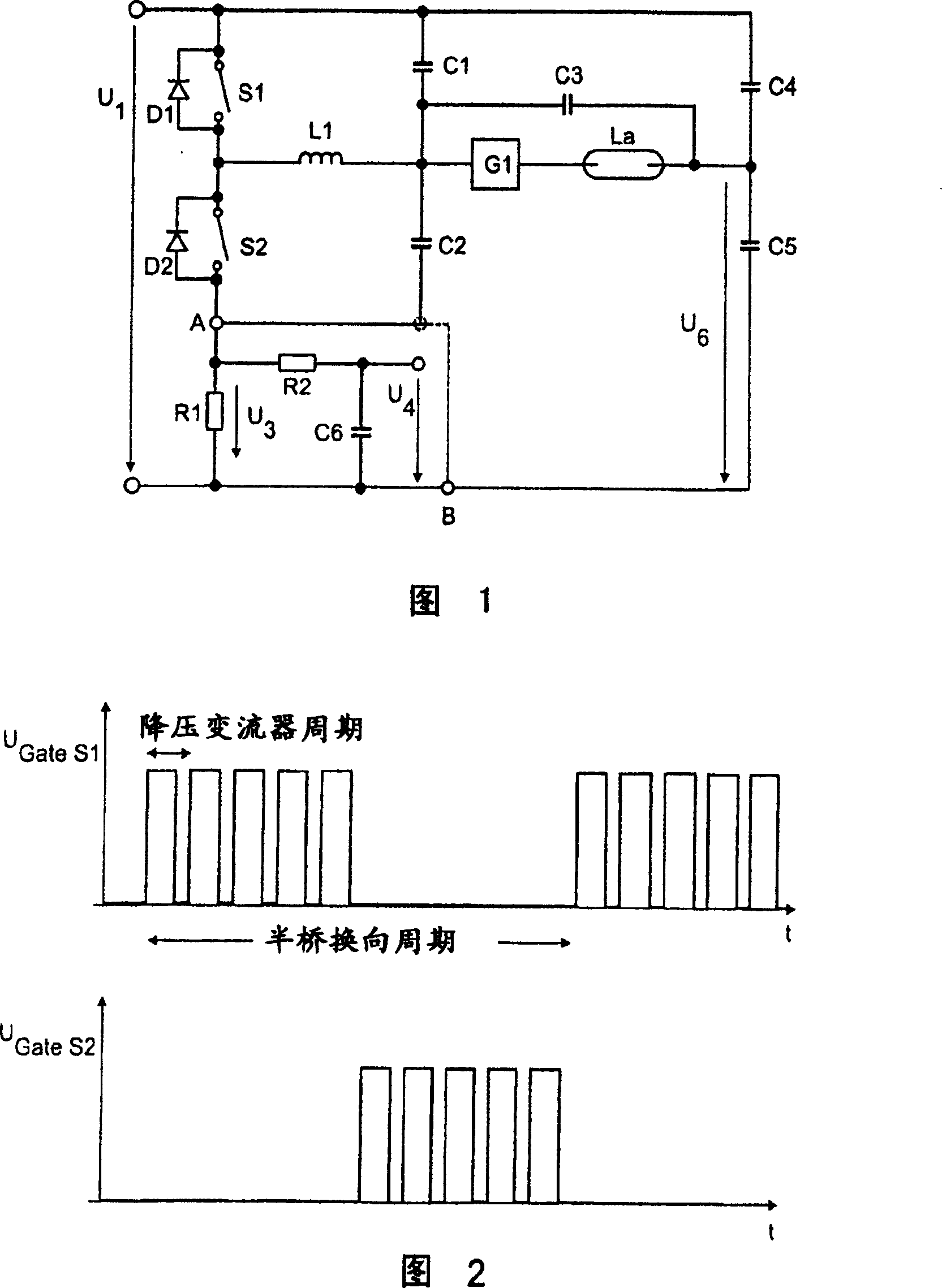
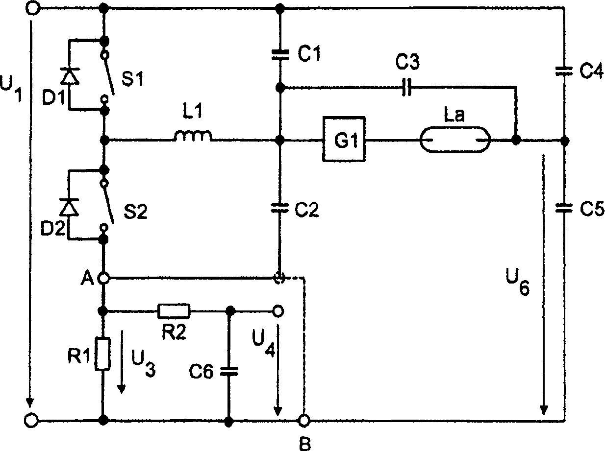
[0021] figure 1 denoted per se well known with two switching transistors S 1 and S 2 Half-bridge topology diagram. The switching transistor S 1 and S 2 Series connection between two supply branches between which the intermediate circuit voltage U is applied 1 . The intermediate circuit voltage U is generated by rectification and corresponding filtering of the system voltage and power factor correction by means of a step-up converter 1 .

[0022] Since the half-bridge transistor S 1 and S 2 The alternating switching operation of the two, the center tap between them switches back and forth between the potentials of the power branches. Accordingly, a high-frequency alternating potential corresponding to this switching operation is applied to figure 1 The inductance L shown 1 left terminal. Inductance L 1 with high pressure discharge lamps, part G 1 connected in series, the inductance L 1 Parts G connected to high-pressure discharge lamps 1 Represents the already w...


PUM


Abstract

The invention relates to an electronic ballast and to an operating method for high-pressure discharge lamps. During a current measurement, in particular for current regulation, only switching phases of a specific polarity of the current are taken into consideration.

Description

technical field [0001] The invention relates to an electronic ballast for a high-pressure discharge lamp and a corresponding operating method. Background technique [0002] The operation of high-pressure discharge lamps using electronic ballasts is conventional in itself. Such ballasts include converters, often half-bridge converters with two switching transistors and full-bridge converters with four switching transistors. During continuous operation of the lamp, these converters, in brief, generate a DC voltage supply for the lamp which alternates at low frequency in their polarity. In the case of this purely DC operation, interference phenomena which occur in the lamp due to asymmetry are avoided, but at the same time the higher frequencies of the interference are substantially isolated from the lamp. [0003] In the case of these ballasts, it is also known to measure the lamp current in order to provide, for example, a safety cut-off when certain threshold values ​​are ...

Claims


Application Information

Patent Timeline
Patent Type & Authority Patents(China)
IPC IPC(8): G01R19/00H05B41/288
CPCH05B41/288H05B41/2825H05B41/2883H05B41/2887Y02B20/202Y02B20/00
Inventor A·布劳恩W·林默J·米尔施勒格尔M·齐格勒
Owner PATENT TREUHAND GESELLSCHAFT FUR ELECTRIC GLUEHLAMPEN MBH
Why Eureka
Try Eureka