Vacuum die casting system and exhaust method thereof

A vacuum die-casting and vacuum tank technology, applied in the vacuum die-casting system and its exhaust field, can solve the problems of large gas flow resistance, small cross-sectional area, and high maintenance costs, and achieve improved quality and performance, improved production efficiency, and reduced production. cost effect

Active Publication Date: 2013-05-15
GUANGDONG INST OF NEW MATERIALS
View PDF6 Cites 2 Cited by
  • Summary
  • Abstract
  • Description
  • Claims
  • Application Information

AI Technical Summary

Problems solved by technology

It is not difficult to see that in the first method, the liquid metal stops exhausting when it reaches the entrance of the cavity, and a part of the gas remains; It is the whole process of exhausting, and it is difficult to fully exhaust the gas; the third method can realize the full exhausting of the whole process, and there is no waste solidified in the toothed exhaust channel in the second method, which is so far the ideal However, the vacuum valve takes a very short time from getting the signal to close the valve to the time when the valve is completely closed, calculated in milliseconds. The operation process is often blocked, and the one-time cost of the valve is high. Regular maintenance is required, and the maintenance cost is also high. The quality requirements of personnel are also high, these factors limit the wide application of this system in vacuum die casting

Method used


Image

  • Vacuum die casting system and exhaust method thereof
  • Vacuum die casting system and exhaust method thereof
  • Vacuum die casting system and exhaust method thereof

Examples


Embodiment Construction

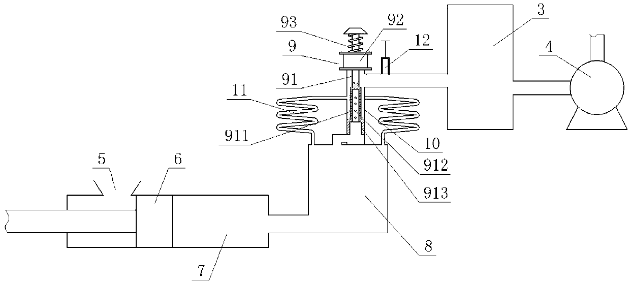
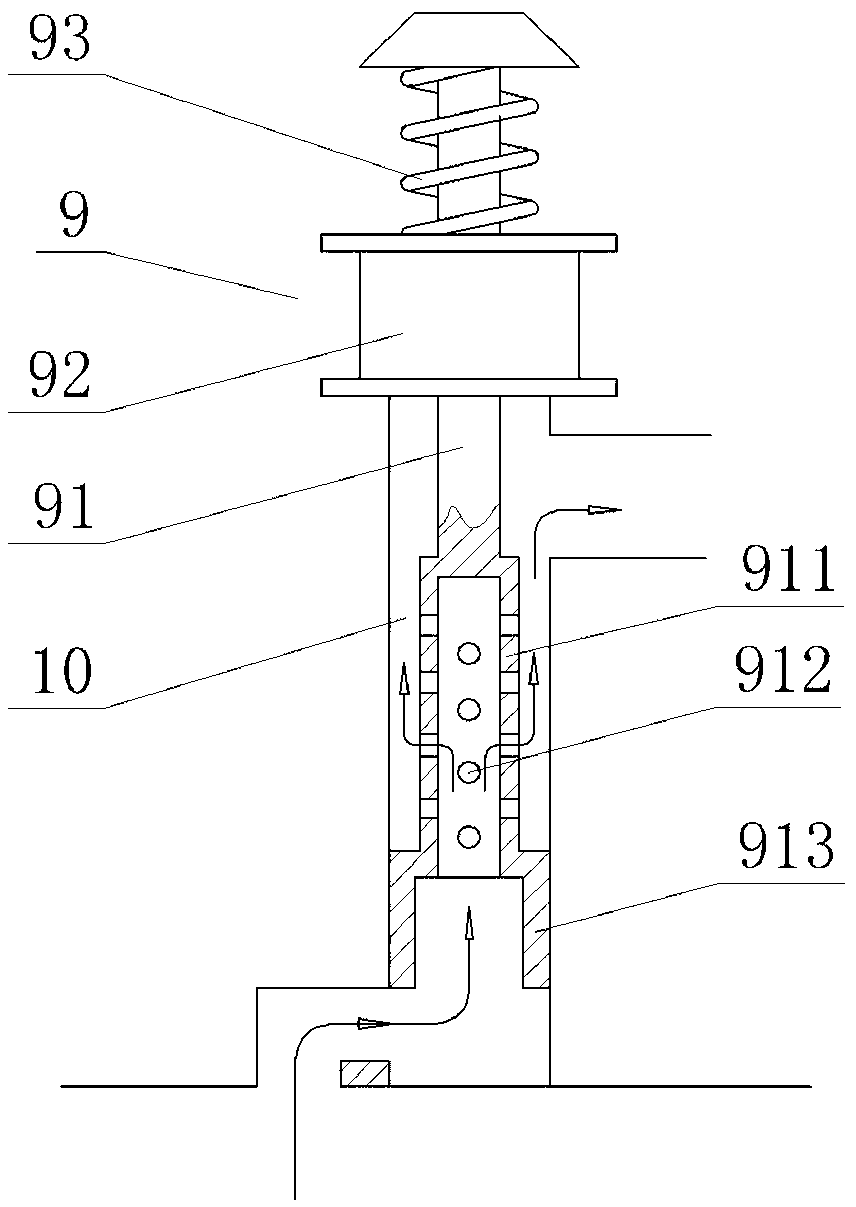
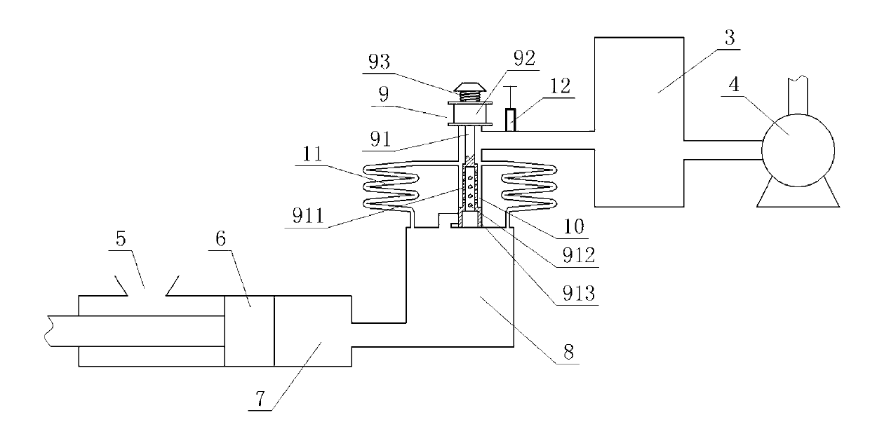
[0022] Such as Figure 1-Figure 7 As shown, the vacuum die-casting system of the present invention includes a PLC control device, a mold 1, an injection device, an exhaust device and a vacuum pumping device, wherein the injection device communicates with the cavity 8 of the mold 1, and the The exhaust device includes a half-process exhaust channel 10 and a toothed exhaust channel 11, which are arranged on the mold 1 and connected with the mold cavity 8 of the mold 1 and the vacuum pumping device. connected, and a master valve 12 is provided between the semi-process exhaust channel 10 and the toothed exhaust channel 11 and the vacuum device, and a normally open semi-process exhaust channel is inserted into the semi-process exhaust channel 10 A solenoid valve 9, the normally open semi-process exhaust solenoid valve 9 is electrically connected to the PLC control device. Wherein, the above-mentioned normally open semi-process exhaust solenoid valve 9 includes a valve stem 91, an ...


PUM


Abstract

A vacuum die casting system and an exhaust method of the vacuum die casting system comprise a programmable logic controller (PLC) control device, a die, a press injection device, an exhaust device and a vacuum suction device, wherein the exhaust device comprises a semi-process exhaust channel and a dentate exhaust channel, main valves are arranged among the semi-process exhaust channel, the dentate exhaust channel and the vacuum suction device, and a normally opened type semi-process exhaust solenoid valve is connected in the semi-process exhaust channel in an inserted mode. Due to the fact that an exhaust structure that exhaust is carried out through the combination of the semi-process exhaust channel and the dentate exhaust channel is adopted, compared with the existing semi-process exhaust, the redundant gas of the semi-process exhaust can be exhausted completely, compared with the existing dentate exhaust channel, the semi-process exhaust which can exhaust most of gas is additionally utilized, the roles of the existing semi-process exhaust and the dentate exhaust channel are fully played, and defects of the existing semi-process exhaust and the dentate exhaust channel are overcome. Therefore, the vacuum die casting system and the exhaust method of the vacuum die casting system can rapidly exhaust the gas completely, and the quality and the performance of die casting products are greatly improved.

Description

technical field [0001] The invention relates to the technical field of vacuum die-casting, in particular to a vacuum die-casting system and an exhaust method thereof. Background technique [0002] Vacuum die-casting technology is based on the traditional pressure casting technology supplemented by the technology of vacuuming the cavity. In the current vacuum die-casting technology, there are three main methods of vacuuming. The first is when the injection punch passes the gate, When the induction switch is touched, the cavity and the pressure chamber are connected to the vacuum source, the gas is pumped out, and the injection punch continues to move forward. Before the rapid injection, the vacuum valve is closed by the travel switch or the time relay, the pumping is stopped, and the punch shoots quickly. , to complete liquid metal filling, this method is also called semi-process exhaust; the second method is to use a "washboard" shaped cooling block, also known as "toothed e...

Claims


Application Information

Patent Timeline
Patent Type & Authority Applications(China)
IPC IPC(8): B22D17/00
Inventor 戚文军宋东福蔡畅黄正华农登王顺成王娟魏德芳
Owner GUANGDONG INST OF NEW MATERIALS
Why Eureka
Try Eureka