
Granulator for producing a granulate made of molten plastic

A granulator and rotor technology, applied in the field of granulators, can solve the problems of large structural complexity of driving motors and templates

Inactive Publication Date: 2009-09-09
MASCHINENFABRIK RIETER AG
View PDF7 Cites 0 Cited by
  • Summary
  • Abstract
  • Description
  • Claims
  • Application Information

AI Technical Summary

Problems solved by technology

Apart from the fact that, as stated, the principles discussed in this publication are used only in conjunction with the cutter head being pressed against the template, such a construction also results in a considerable distance between the drive motor and the template. structural complexity

Method used


Image

  • Granulator for producing a granulate made of molten plastic
  • Granulator for producing a granulate made of molten plastic

Examples


Embodiment Construction

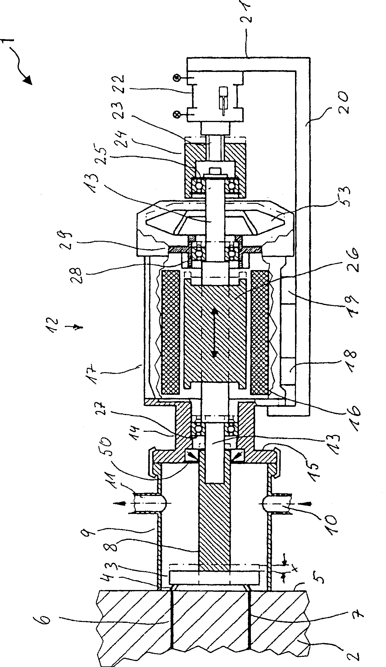
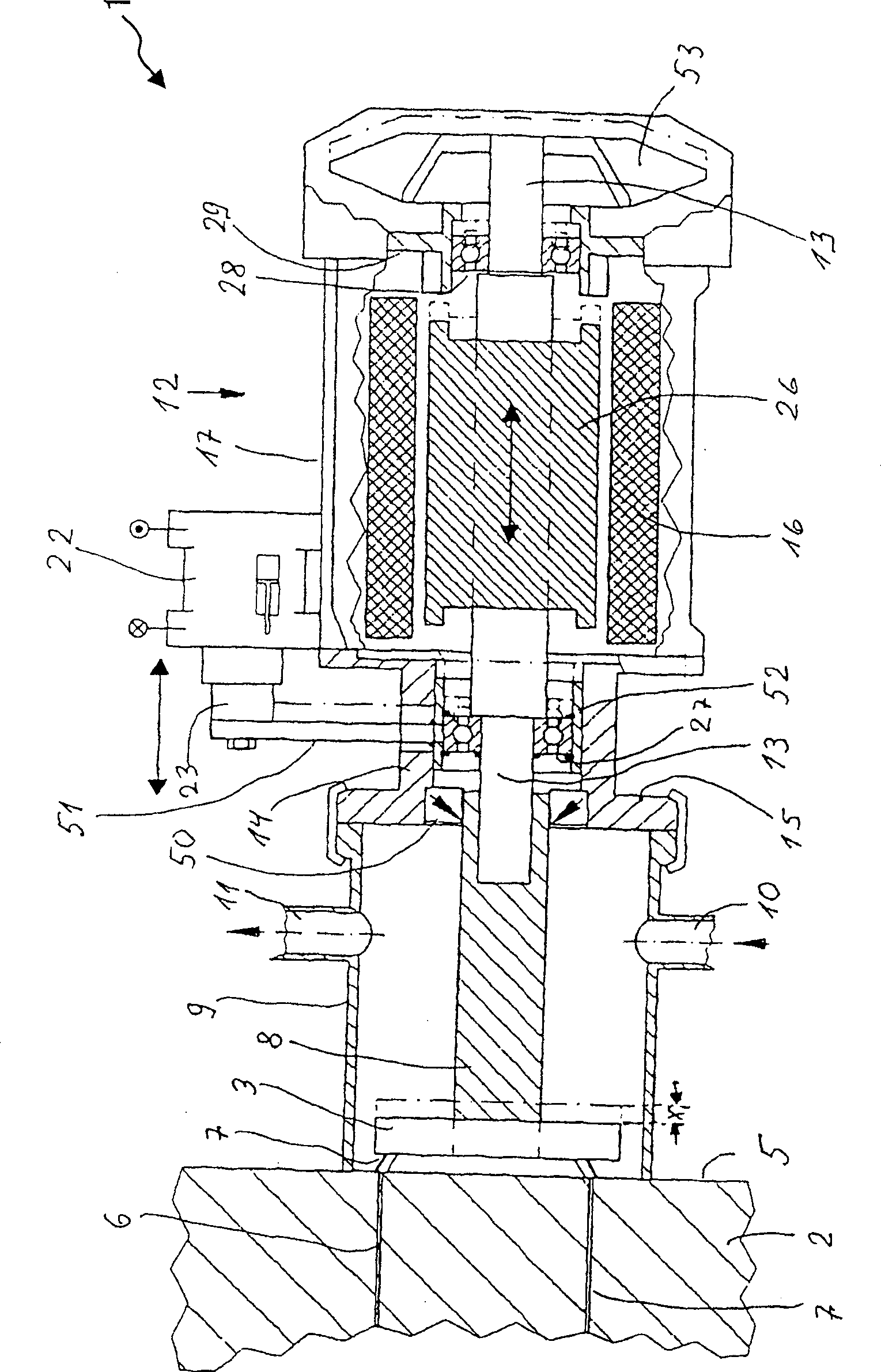
[0016] figure 1 A pelletizer 1 with a template 2 and a rotating cutter head 3 is shown. The cutter 4 of the cutter head 3 sweeps the conveying side 5 of the template 2 and cuts the plastic melt emerging from the nozzles 6 and 7 to form particles. The template 2 contains a large number of annularly arranged nozzles 6 and 7, wherein the large number of nozzles 6 and 7 are figure 1 The middle is not visible. This design is a well-known structure.

[0017] The rotor shaft 8 rotates the cutter head 3, wherein the rotor shaft 8 is housed in the housing 9 together with the cutter head 3 and the cutter 4, and the housing 9 is subjected to a throughflow of a cooling medium, which flows into the inlet 10 and out through the outlet 11, the cooling liquid takes away the particles that have been cut by the cutter 4 and transports the particles to the outside of the housing 9. The housing 9 is fixedly connected to the template 2.

[0018] The rotor shaft 8 is connected to the drive shaft 13 ...


PUM


Abstract

A drive motor rotor(26) can be axially moved over an adjustment range(x) in relation to the motor stator(16) fixed to the die plate(7). Movement is effected by an adjuster(22) mounted between the rotor and a supporting frame(20) connected to the die plate. Alternatively the entire drive motor(12) is moved axially by the adjuster and can be held in any set position. The drive rotor(26) is mounted in the stator(16) in low friction bearings(27,28) at both ends. Outer rings of the bearings are axially movable within a housing(14,29) of the drive motor. The drive motor(26) is supported on the linear adjuster(22) via a rotation decoupler(24,25) and the adjuster is located on the rear side of the rotor facing away from the granulating blade head(3). The linear adjuster is on the rear side of the drive rotor relative to the blade head. In the alternative design a supporting frame for the drive motor is mounted on a linear guide and is connected to the linear adjuster.

Description

Technical field [0001] The present invention relates to a pelletizer that produces particles from molten plastic using a cutter head that can be displaced within an adjustable range. The cutter head cooperates with a template for distributing plastic melt. The cutter head is connected to a stator and a driving rotor. The inner drive motor is on the drive shaft and can be axially displaced relative to the template. Background technique [0002] According to the prior art, in such a granulator, for example, the principle published in DE 4408235 C1 is used to perform the axial displacement of the cutter head, whereby the cutter shaft coaxial with the drive motor shaft is fixed by the drive motor through coupling The intermediate piece is axially displaced, the cutter head is mounted to the end of the cutter shaft facing away from the drive motor, and the cutter head cooperates with the template. The axis displacement of the tool axis is firstly to compensate for the wear that occurs...

Claims


Application Information

Patent Timeline
Patent Type & Authority Patents(China)
IPC IPC(8): B29B9/06H02K7/12B01J2/00B29D99/00
CPCB29B9/06H02K7/12B29B9/065B01J2/00
Inventor 林哈特·卡斯滕·穆布
Owner MASCHINENFABRIK RIETER AG
Learn More