Master-slave synchronization communication method
A technology of synchronous communication and master device, which is applied in the direction of synchronous device, multiplex communication, and branch office to provide special service devices, etc., and can solve the problems of fixed inherent period and so on
- Summary
- Abstract
- Description
- Claims
- Application Information
AI Technical Summary
Problems solved by technology
Method used
Image
Examples
no. 1 example
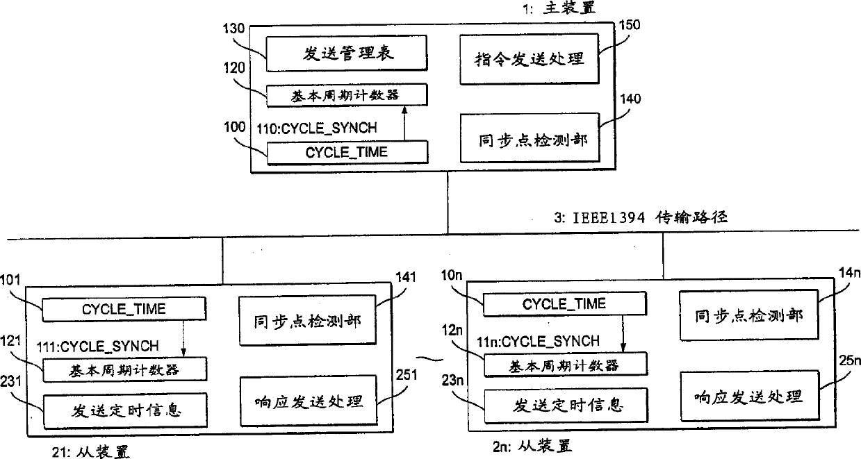
[0060] First, the functional part names and signal names specified in the IEEE1394 standard appearing in the following description will be explained. As shown in FIG. 5, the CYCLE_TIME register includes a cycle_offset part, a cycle_count part, and a second_count part. The cycle_offset unit counts the 24.576 MHz clock in each station. When the count reaches 3072, that is, every 125μs of the natural cycle, the cycle_offset section outputs a carry. The cycle_count section counts the carry from the cycle_offset section. When the count reaches 8000, that is, every time ls passes, the cycle_offset part outputs a carry. Cycle_synch is a synchronization signal issued every natural cycle 125 μs.
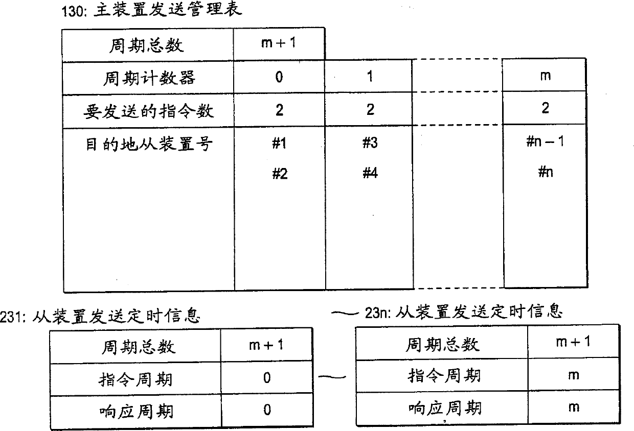
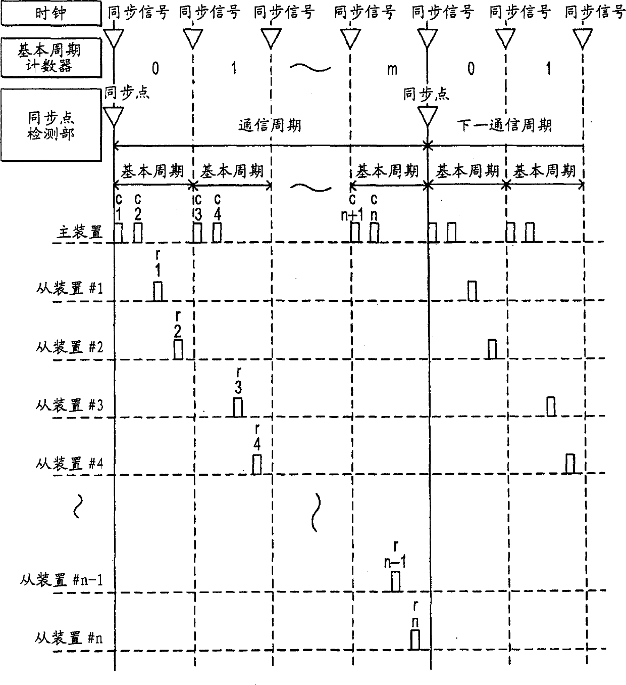
[0061] FIG. 1 shows a specific embodiment of the first invention, wherein reference numeral 1 represents a master device, reference numeral 2i (i=1, 2, . . . , n) represents a slave device, and reference numeral 3 represents a transmission path of IEEE1394. Reference numeral 10j (j=0, 1, ...
no. 2 example
[0072] Next, an embodiment of the synchronization point detecting section 14j that synchronizes the updating of the fundamental period counter 12j will be described. In fact, the detection of the synchronization point is performed separately for the master device 1 and each slave device 2i, and the result is reflected in the value of the basic cycle counter 12j of each station. The period used as its synchronization point requires the same determination result from all stations. Although in the present embodiment, the value of the basic cycle counter 12j is 0 at this synchronization point, and the value of the basic cycle counter 12j is all incremented every time a basic cycle is passed (that is, the Cycle_synch event 11j occurs), and the basic cycle counter 12j The value of is returned to 0 at the next synchronization point after a predetermined communication cycle elapses, however, the switching of the value of the basic cycle counter 12j is not limited thereto, for example,...
no. 3 example
[0076] The third invention will be described as another method of the synchronization point detection processing 14j. In the synchronization point detection process 140 of the master device 1, the synchronization point detection section is started by the Cycle_synch event 11j every natural cycle, and only the basic cycle counter 120 is incremented and it is determined whether the value is 0 or not. The command data transmitted from the master to each slave according to the transmission management table includes the CYCLE_TIME register value of the next synchronization point.
[0077] Processing in each slave device 2i will be described along with FIG. 9 . First, at S4000, the process determines whether command data from the master device 1 was received in the last basic cycle. In the case of receiving data, the process extracts the CYCLE_TIME register value as the next synchronization point in the received command data at S4001. Next, at S4002, the process obtains the differ...
PUM
 Abstract
Description
Claims
Application Information
 - R&D
- Intellectual Property
- Life Sciences
- Materials
- Tech Scout
- Unparalleled Data Quality
- Higher Quality Content
- 60% Fewer Hallucinations
Browse by: Latest US Patents, China's latest patents, Technical Efficacy Thesaurus, Application Domain, Technology Topic, Popular Technical Reports.
© 2025 PatSnap. All rights reserved.Legal|Privacy policy|Modern Slavery Act Transparency Statement|Sitemap|About US| Contact US: help@patsnap.com


