Supercharge Your Innovation With Domain-Expert AI Agents!

Mesovalve modulator

A controller and flow sensor technology, applied in diaphragm valves, valve devices, valve details, etc., can solve problems such as the inapplicability of electrostatic actuators, and achieve the effect of delaying or avoiding the pull-in effect

Inactive Publication Date: 2006-09-06
HONEYWELL INT INC
View PDF7 Cites 1 Cited by
  • Summary
  • Abstract
  • Description
  • Claims
  • Application Information

AI Technical Summary

Problems solved by technology

However, pull-in effects can appear after this displacement
Many techniques are used to delay or avoid this phenomenon, making many electrostatic actuators unsuitable for many applications

Method used


Image

  • Mesovalve modulator
  • Mesovalve modulator
  • Mesovalve modulator

Examples


Embodiment Construction

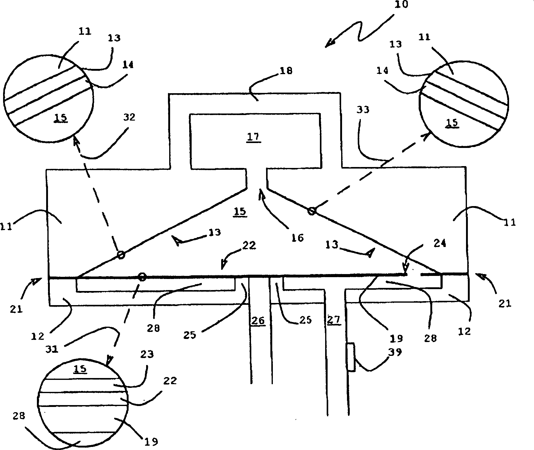
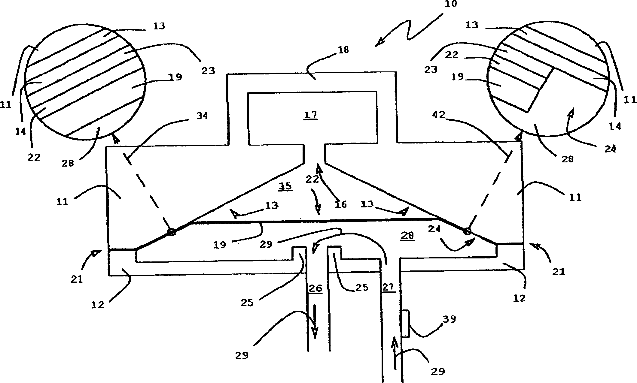
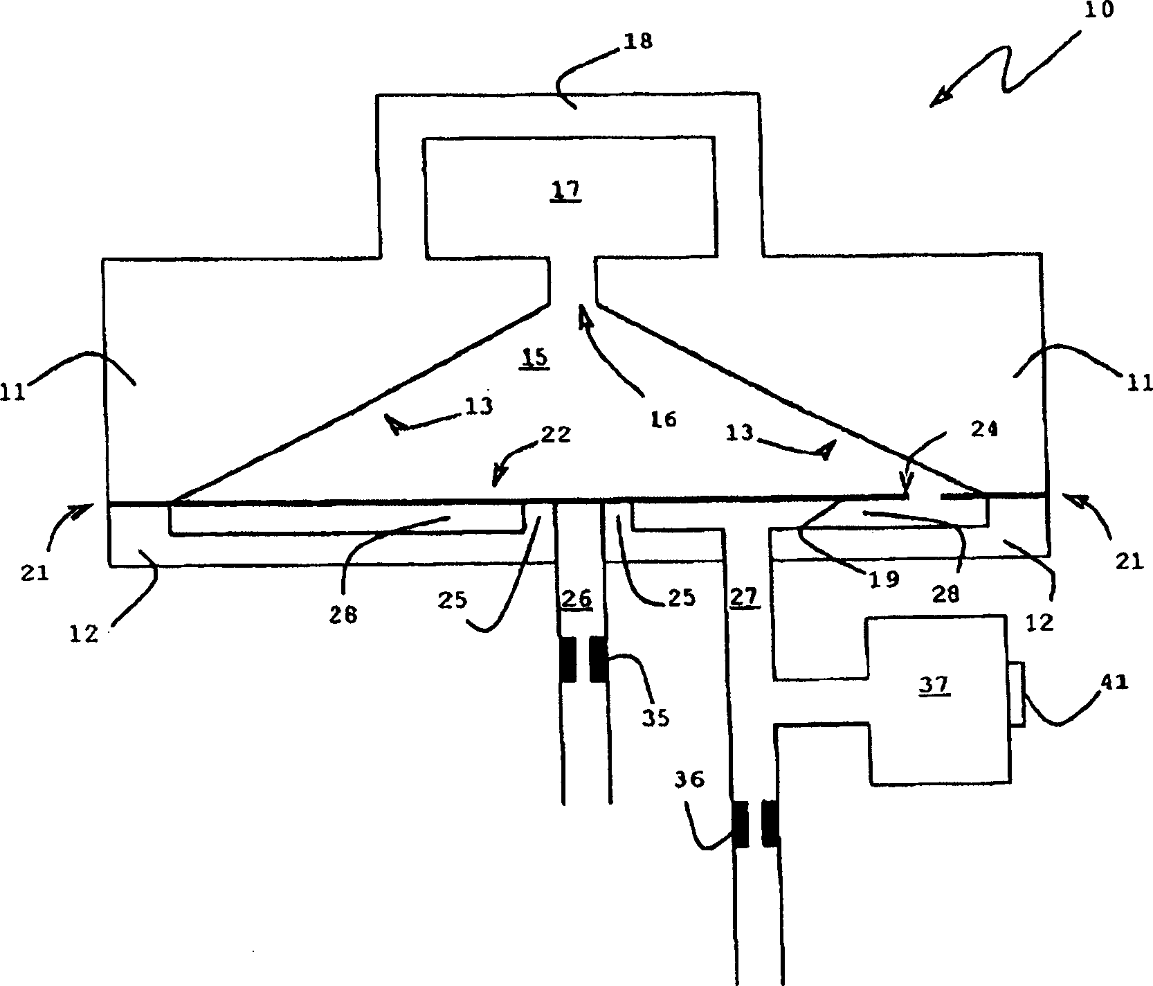
[0008] In an electrostatic modulator, electrostatic forces operate against the force holding the two electrodes of the actuator apart. This force can be produced by elastic, pneumatic or similar forces. By applying a drive voltage, the position of the actuator can be controlled to a third of the initial distance between the electrodes, and a pull-in (embedding) effect then occurs. For a certain range of drive voltages, this control can be achieved until the threshold is pulled in. Such a threshold can be small and therefore does not provide good results for controlling the drive voltage and makes control difficult. If the force holding the electrodes apart increases as the electrodes are displaced, the pull-in effect can occur at a third of the displacement, but at a higher threshold. For the control of electrostatic actuators, a higher voltage control range provides higher resolution. The invention can be an intermediate valve which avoids the pull-in effect for very high ...


PUM


Abstract

The invention provides a electrostatic valve, which comprises: the first structure with entrance and exit; membrane, located above the first structure to form the first cavities; the second structure, located above membrane to form the second cavities; the first electrode connected with membrane; and the second electrode connected with inner surface of the second structure; wherein membrane has a open-end between the first cavities and the second cavities, and the open-end can be closed.

Description

technical field [0001] The present invention relates to valves, and in particular to electrostatically actuated valves. More particularly, the present invention relates to electrostatically actuated valves for modulation. Background technique [0002] A related patent application to this invention is US Patent Application 10 / 174,851, filed June 19, 2002, which is incorporated herein by reference. Patents that may be relevant to the present invention include US Patent 6,288,472, US Patent 6,179,586, US Patent 6,106,245, US Patent 5,901,939, US Patent 5,836,750, and US Patent 5,822,170. All of these patents are hereby incorporated by reference. This application may be related to Bonne et al., entitled "Electrostatically Actuated Gas Valve," Attorney No. H0003388-765 (1161.116701), filed at approximately the same time, and to Cabuz et al., entitled "Media Isolation Electrostatically Actuated Gas Valve." Valve" and patent application Attorney No. H00075707 (1100.1283101), whi...

Claims


Application Information

Patent Timeline
IPC IPC(8): F16K7/14F16K31/02H02N1/00
CPCF16K7/14F16K31/02Y10T137/7759Y10T137/0396Y10T137/785Y10T137/7761
Inventor E·I·卡布斯C·卡布斯C·巴纳
Owner HONEYWELL INT INC
Features
  • R&D
  • Intellectual Property
  • Life Sciences
  • Materials
  • Tech Scout
  • Unparalleled Data Quality
  • Higher Quality Content
  • 60% Fewer Hallucinations
Learn More