

Liquid film colliding type jet reactor
A jet reactor, impingement technology, applied in chemical/physical/physical-chemical stationary reactors, chemical/physical/physical-chemical nozzle reactors, fluid mixers, etc.
- Summary
- Abstract
- Description
- Claims
- Application Information
AI Technical Summary
Problems solved by technology
Method used
Image

Examples
Embodiment approach A
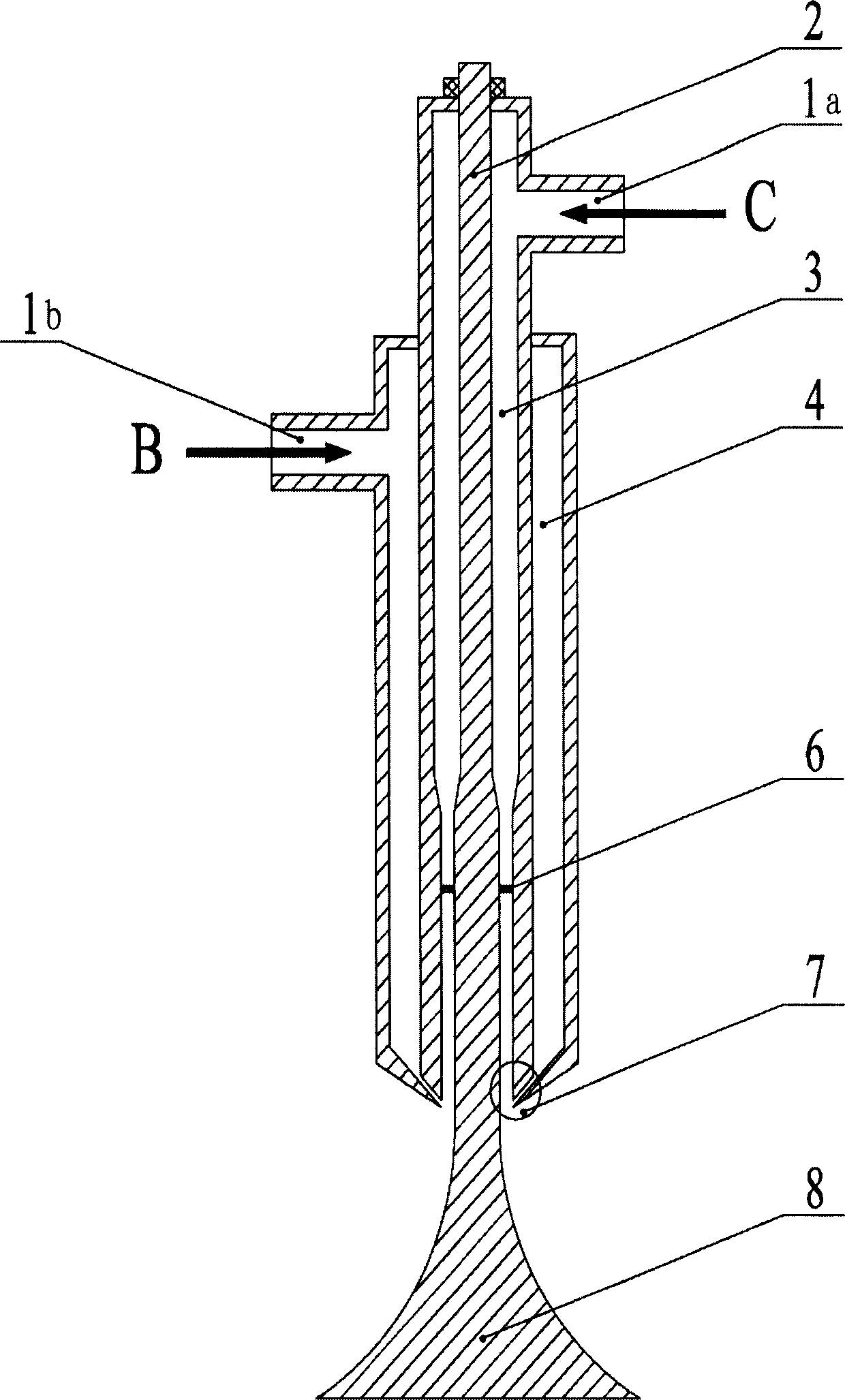
[0040] Such as image 3 As shown, the reactor includes feed inlets 1a and 1b, central shaft 2, inner ring pipe 3, middle ring pipe 4 and mixing head 8; said central shaft 2, inner ring pipe 3 and middle ring pipe 4 are from inside to outside shaft setting; the mixing head 8 is connected to the lower end of the central shaft 2; an inner ring gap is formed between the lower end of the inner ring tube and the central shaft, and a middle ring gap is formed between the lower end of the middle ring tube and the lower end of the inner ring tube.
[0041] image 3 The reactor shown works as follows: two streams of raw materials C and B are injected into the inner ring pipe 3 and the middle ring pipe 4 of the reactor through feed ports 1a and 1b respectively, and flow down along the inner ring pipe and the middle ring pipe. Raw materials C and B respectively pass through the inner ring gap and the middle ring gap with a thickness of several millimeters, and the liquid films formed by ...
Embodiment approach B
[0043] Such as Figure 4 As shown, the reactor includes feed inlets 1a, 1b and 1c, central shaft 2, inner ring pipe 3, middle ring pipe 4, outer ring pipe 5 and mixing head 8; said central shaft 2, inner ring pipe 3, middle ring The pipe 4 and the outer ring pipe 5 are arranged coaxially from the inside to the outside; the mixing head 8 is connected to the lower end of the central axis 2; A middle ring gap is formed between the lower ends of the ring pipes, and an outer ring gap is formed between the lower ends of the outer ring pipe and the lower ends of the middle ring pipe.
[0044] Figure 4 The reactor shown works as follows: three strands of raw materials C, B and A are injected into the inner ring pipe 3, the middle ring pipe 4 and the outer ring pipe 5 of the reactor through the feed ports 1a, 1b and 1c respectively, and Pipe, middle pipe and outer pipe flow downward. Raw materials C, B and A respectively pass through the inner ring gap, the middle ring gap and the ...
Embodiment approach C
[0046] The structure of the reactor is as Figure 4 shown. The difference from embodiment B is that this embodiment only processes two streams of raw materials, wherein raw material C is injected into the inner ring pipe 3 and outer ring pipe 5 through the feed port 1a and 1c respectively, and raw material B is injected through the feed port 1b Central tube 4. The rest of the reaction process is the same as Embodiment B. Such a logistics arrangement enables more thorough mixing and reaction of the two liquid streams.
PUM
| Property | Measurement | Unit |
|---|---|---|
| Thickness | aaaaa | aaaaa |
| Thickness | aaaaa | aaaaa |
Abstract
Description
Claims
Application Information