Coiling device for coiling for knitting machine

A loop forming device, knitting machine technology, applied in knitting, textiles and papermaking, etc.

Inactive Publication Date: 2010-09-29
GROZ BECKERT KG
View PDF4 Cites 0 Cited by
  • Summary
  • Abstract
  • Description
  • Claims
  • Application Information

AI Technical Summary

Problems solved by technology

[0006] Known from DE 29 09 963 C2 is a method for machine knitting in which, although an upwardly directed transfer hook is used, only Inward movement perpendicular to the needle, making it possible under the transfer hook to attach particles through the formation of flying flowers, which interfere with the transfer of the coil
Safety problems caused by errors in the needle channel of the machine when the loop is received on the transfer hook also make this known method impractical up to now

Method used


Image

  • Coiling device for coiling for knitting machine
  • Coiling device for coiling for knitting machine
  • Coiling device for coiling for knitting machine

Examples


Embodiment Construction

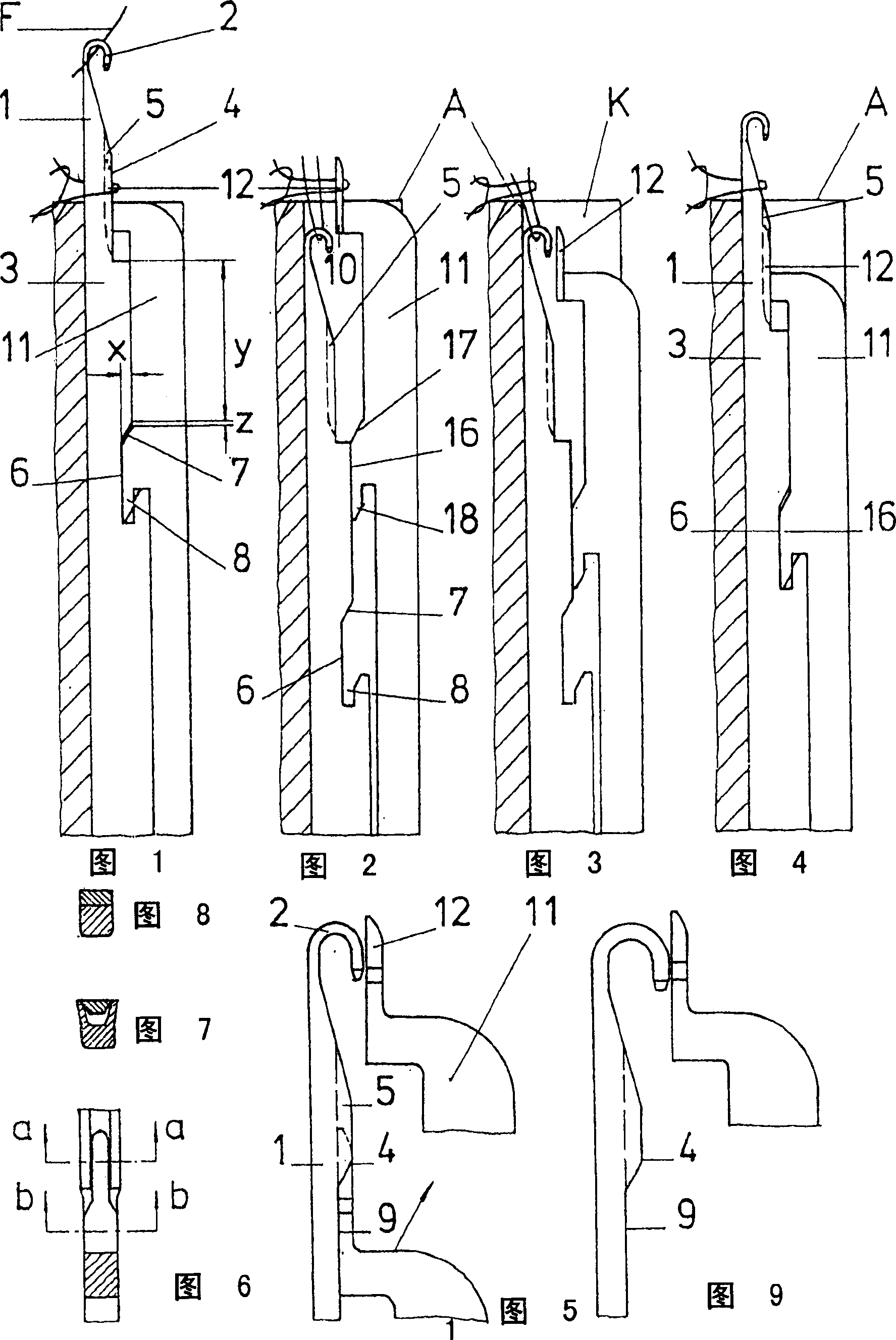
[0053] figure 1 Shown is needle 1 with needle shaft 3 and needle hook 2, which has received a thread F. An upwardly directed transfer hook 12 is arranged with its shaft 11 in operative connection with the needle hook 2 . The shaft 3 of the needle 1 has a notch 6 which is in contact with the finger-shaped projection 16 of the transfer hook 12 ( figure 2 )correspond. The recess 6 on the shaft of the needle 1 ends at the top with a riser 7 and at the bottom with a partially inclined notch 8 . At the same inclined finger-shaped portion 18 ( figure 2 ) together, this sliding surface facilitates engagement on both sides. The raised surface 7 on the needle shaft 3 and the beveled point 17 on the transfer hook shaft 11 are also arranged such that they are operatively connected when the needle 1 and the shaft of the transfer hook 12 are in a defined position.

[0054] There is a gap 8 below the rising surface 7 on the needle bar 3 . When the needle 1 and the transfer hook 12 a...


PUM


Abstract

The invention relates to a knitting or warp knitting machine for machine knitting with at least one continuous thread, said machine comprising knitting elements (1, 12). The aim of the invention is to simplify said knitting elements and the control system thereof for extended design applications with high levels of performance and safety, and to increase the stability of the transfer hook with a self-cleaning effect during the insertion thereof into the notch of the needle for fine needle intricacies. To this end, said knitting elements are connected by coupling elements (6, 16) by which means the inward transversal movement of the upwardly oriented transfer hook (12) can be controlled inside the needle slot (in warp knitting machines) or beneath the evener comb during the forward movement, in such a way that after leaving the loop sinking position of the needle (1) and releasing the old knitting loop from the transfer hook (12), the knitting elements (1, 12) can be moved upstream together into the upper position thereof, such that the control end of the transfer hook (12) catches the coupling impact of the needle (1) by means of a synchronous incline in the machine lock.

Description

technical field [0001] Devices for machine looping with at least one continuous yarn have been known, wherein the yarn is passed through a previously formed loop as a loop respectively by means of a knitting needle or a hook portion of the needle and a new loop is formed. the coil. Background technique [0002] In one arrangement (DE 101 12 277 C1), the walls of a needle channel each have a recess open upwards, which forms a vertical sliding edge. In addition, the knitting needle or needle is supported and formed in the needle channel so that it can be returned by a vertical edge on the side of the center point of the notch via a transfer hook movable in the longitudinal and vertical direction. [0003] In another device of this type (DE 101 52 856 C1), the knitting needle or needle has a needle slot below the needle hook into which a downwardly directed transfer hook movable in the horizontal and vertical direction can be pushed. inside the needle slot. In this arrangem...

Claims


Application Information

Patent Timeline
Patent Type & Authority Patents(China)
IPC IPC(8): D04B35/06
CPCD04B35/06D04B35/00
Inventor U·霍夫曼
Owner GROZ BECKERT KG
Why Eureka
Try Eureka