Satellite optical communication high precision advance sighting angle compensating device
A satellite optical communication, angle compensation technology, applied in satellite communication transmission, electromagnetic wave transmission system, electrical components and other directions, can solve the problems of complex actuator and slow speed
- Summary
- Abstract
- Description
- Claims
- Application Information
AI Technical Summary
Problems solved by technology
Method used
Image

Examples
specific Embodiment approach 1
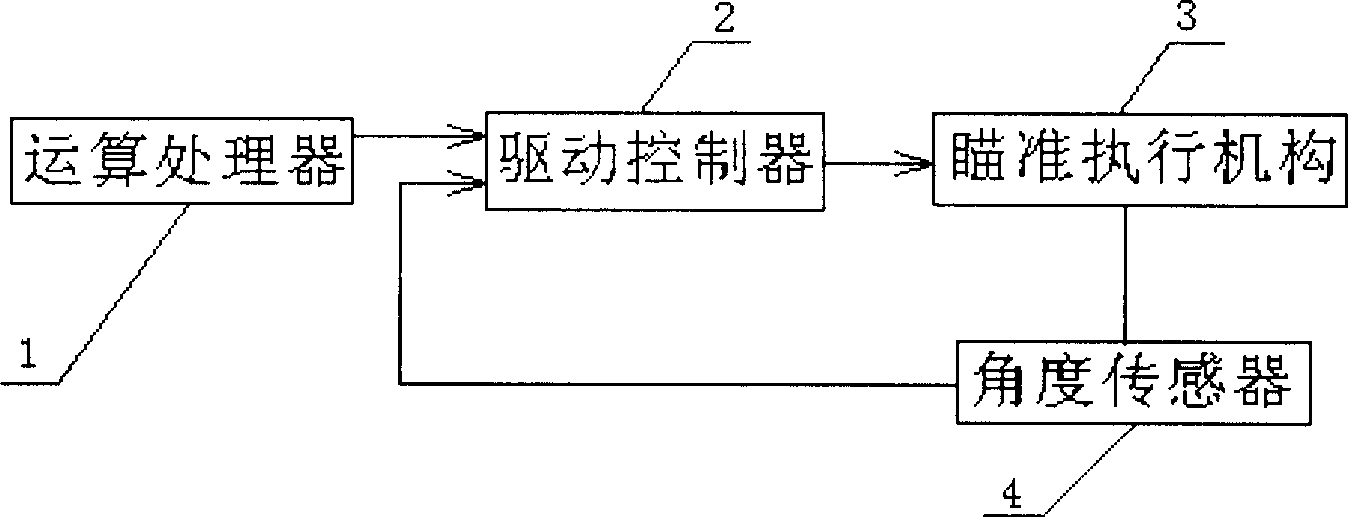
[0005] Specific implementation mode one: the following combination figure 1 , figure 2 with Figure 5 This embodiment will be specifically described. This embodiment is composed of an arithmetic processor 1, a drive controller 2, an aiming actuator 3 and an angle sensor 4, and the output terminal of the arithmetic processor 1, which can calculate the current point-in-advanced aiming angle value through the orbit data of the satellite, is connected to the drive One input end of the controller 2, the output end of the drive controller 2 is connected to the input end of the aiming actuator 3, the angle sensor 4 is arranged on the aiming actuator 3 to measure its rotation angle in real time, and the output end of the angle sensor 4 is connected to the drive control The other input terminal of device 2 is used to realize angle feedback, and the aiming actuator 3 is composed of No. 1 piezoelectric ceramic column 3-1, No. 2 piezoelectric ceramic column 3-2, worktable body 3-3, wor...
specific Embodiment approach 2
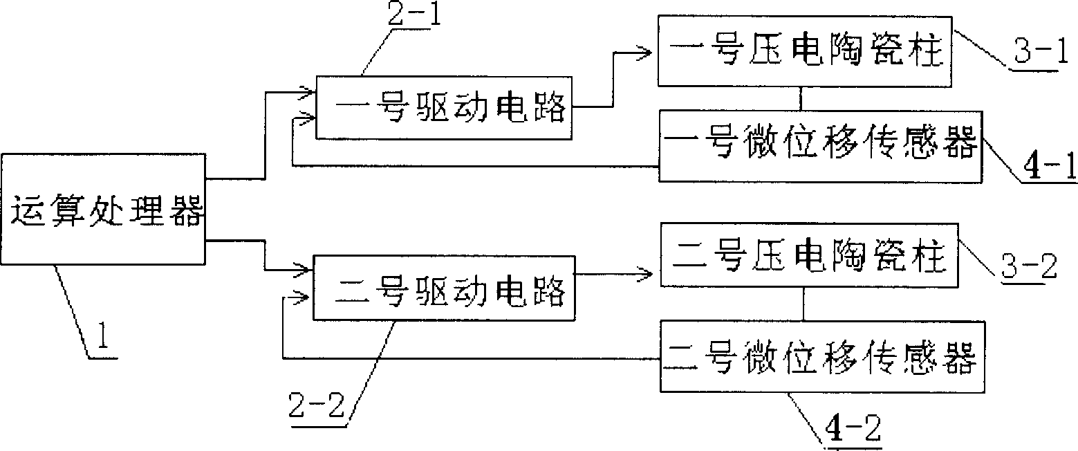
[0006] Specific implementation mode two: the following combination image 3 This embodiment will be specifically described. The difference between this embodiment and Embodiment 1 is: angle sensor 4 is made up of No. 1 micro-displacement sensor 4-1 and No. 2 micro-displacement sensor 4-2, No. 1 micro-displacement sensor 4-1 and No. 2 micro-displacement sensor 4 -2 are all selected resistance strain sensors and built into the No. 1 piezoelectric ceramic column 3-1 and the No. 2 piezoelectric ceramic column 3-2 respectively, and the drive controller 2 is composed of the No. 1 drive control circuit 2- with the same structure. 1 and No. 2 drive control circuit 2-2, one input end of the No. 1 drive control circuit 2-1 is connected to an output end of the arithmetic processor 1, and the other input end of the No. 1 drive control circuit 2-1 is connected to the No. 1 drive control circuit 2-1. The output end of the micro-displacement sensor 4-1, an input end of the No. 2 drive contr...
specific Embodiment approach 3
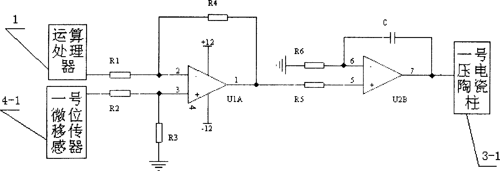
[0007] Specific implementation mode three: the following combination Figure 4 This embodiment will be specifically described. The difference between the present embodiment and the second embodiment is: No. 1 drive control circuit 2-1 is composed of resistor R1, resistor R2, resistor R3, resistor R4, resistor R5, resistor R6, capacitor C, integrated operational amplifier U1A and integrated operational amplifier Composed of U2B, one end of the resistor R1 is connected to an output end of the operational processor 1, the other end of the resistor R1 is connected to one end of the resistor R4 and the inverting input end of the integrated operational amplifier U1A, and the same input end of the integrated operational amplifier U1A is connected to the resistor R3 One end of the resistor R2 and one end of the resistor R3, the other end of the resistor R3 is grounded, the other end of the resistor R2 is connected to the output end of the No. 1 micro-displacement sensor 4-1, and the o...
PUM
 Abstract
Description
Claims
Application Information
 - R&D
- Intellectual Property
- Life Sciences
- Materials
- Tech Scout
- Unparalleled Data Quality
- Higher Quality Content
- 60% Fewer Hallucinations
Browse by: Latest US Patents, China's latest patents, Technical Efficacy Thesaurus, Application Domain, Technology Topic, Popular Technical Reports.
© 2025 PatSnap. All rights reserved.Legal|Privacy policy|Modern Slavery Act Transparency Statement|Sitemap|About US| Contact US: help@patsnap.com