
Radio frequency identification and test system

A radio frequency and test system technology, applied in the field of radio frequency identification test system, can solve the problems that radio is easily affected by metal reflection, the pallet is bulky, and radio frequency identification selection and reading effect are not mentioned.

Active Publication Date: 2006-10-04
IND TECH RES INST
View PDF2 Cites 6 Cited by
  • Summary
  • Abstract
  • Description
  • Claims
  • Application Information

AI Technical Summary

Problems solved by technology

[0007] Yet another related technology is "Radio Frequency Identification Devices and a Method of Determining a Communication Range" of US6452496, which discloses an active radio frequency identification (RFID) volume The target’s internal component structure and its communication distance measurement method, but does not mention the selection of radio frequency identification (RFID) readers, radio frequency identification (RFID) tags, and the combination of the object under test and the reading effect
[0008] In addition, the general logistics site is to fix the radio frequency identification (RFID) reader, and move the object under test and the radio frequency identification (RFID) label by the pallet, and then use the radio frequency identification (RFID) reader to read It is used to measure the reading range of a radio frequency identification (RFID) reader; however, due to the large size of the pallet and the weight of the items on it, if a mechanism is to drive the pallet to move, the mechanism must have A certain structural strength and powerful driving equipment, so metal structures must be used to make the mechanism, but because radio (electromagnetic waves) are easily affected by metal reflections, the measurement results are prone to errors

Method used


Image

  • Radio frequency identification and test system
  • Radio frequency identification and test system

Examples


Embodiment Construction

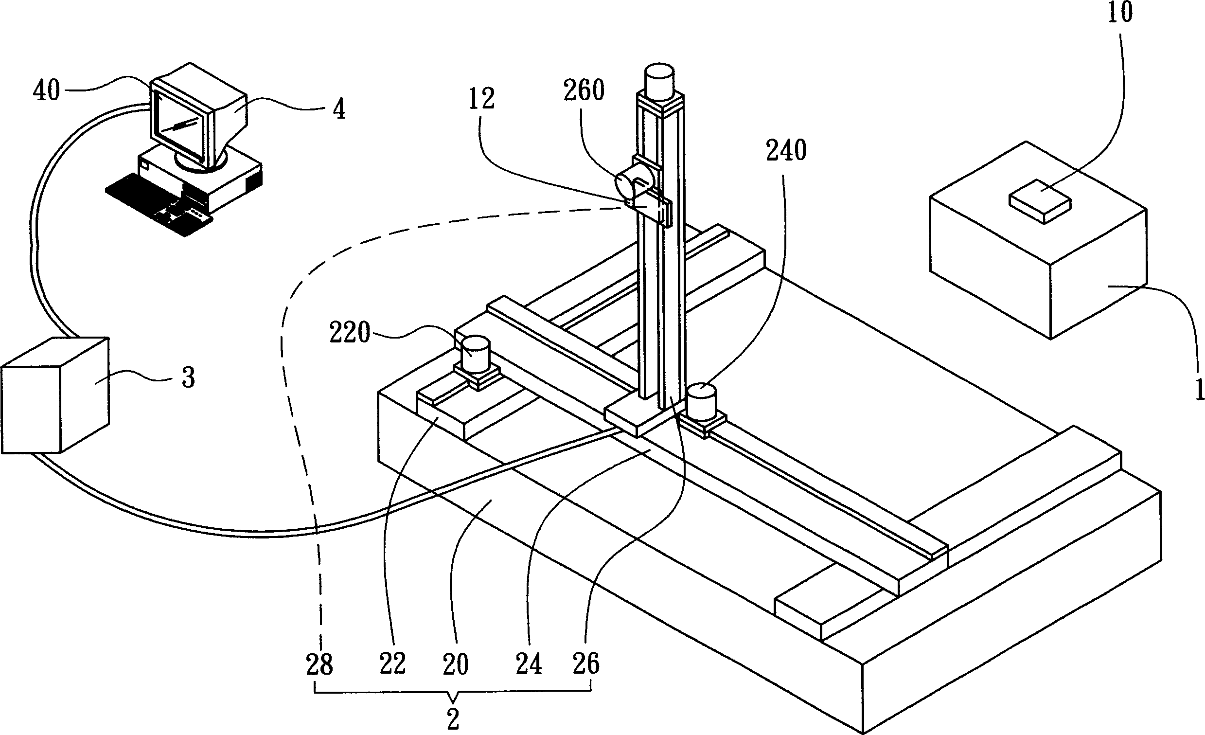
[0031] figure 1 It is a schematic diagram of a radio frequency identification (RFID) testing system of the present invention, showing a preferred embodiment. Wherein the radio frequency identification (RFID) test system includes a test object 1, a testing machine 2 and a radio frequency identification (RFID) reader 12, and the test object 1 is provided with a radio frequency identification (RFID) label 10. The testing machine 2 includes a base 20 , a first slide rail 22 , a second slide rail 24 , a third slide rail 26 and a clamping portion 28 .

[0032] The first sliding rail 22 has an elongated shape and is fixed on the base 20 (of course, the first sliding rail 22 can be integrally formed with the base 20 ).

[0033] The second slide rail 24 has an elongated shape and is located on the first slide rail 22 , the second slide rail 24 is perpendicular to the first slide rail 22 , and the second slide rail 24 is connected to the first slide rail 22 A driving device 220 is di...


PUM


Abstract

The disclosed RFID testing system comprises: a target to be tested with RFID label, a RFID reader, and a testing machine with a base, a first guide rail fixed on base, a second guide rail vertical to the first one for linear movement, a third guide rail with strip shape on the second one and vertical to the first and second ones while fit to linear move on the second one, and a strangulation part connected and moved along the third one and fixed the target or RFID reader.

Description

technical field [0001] The invention relates to a radio frequency identification (RFID) testing system, in particular to a radio frequency identification (RFID) testing system capable of testing the relative relationship between a radio frequency identification (RFID) label and a reader. Background technique [0002] In general, a radio frequency identification (RFID) system can be roughly divided into two parts: a reader (including an antenna), and a radio frequency identification (RFID) tag, in which the reader antenna uses electromagnetic waves to identify radio frequency (RFID) tags for reading or writing. [0003] There are many types of readers and RFID tags on the market. The performance of the readers and the characteristics of the RFID tags are different. The types of antennas attached to the readers are different. The characteristics, reading distance, and reading rate of different items are different. This is because radio frequency identification (RFID) transmit...

Claims


Application Information

Patent Timeline
IPC IPC(8): G06K7/10
Inventor 张维余俊德王圣弼陈士林陈佩君张素惠
Owner IND TECH RES INST
Learn More