Micro RFID tag with conductive interface

a micro-rfid and interface technology, applied in the field of equipment identification and equipment tracking systems, can solve the problems of inability to meet the intended function of the rfid tag, lack of specificity of visual markings, and increased time for workers to accomplish, and achieve the effect of increasing the read range of the micro-rfid tag

Active Publication Date: 2019-07-30
BLANK BRIAN K
View PDF12 Cites 1 Cited by
  • Summary
  • Abstract
  • Description
  • Claims
  • Application Information

AI Technical Summary

Benefits of technology

[0010]Objectives of the subject disclosure include providing a micro RFID tag with a conductive surface to provide increased read range of the micro RFID tag.
[0011]A further objective of the subject disclosure is to provide a micro RFID tag with a conductive surface to provide increased available charge, output power, and read range of the RFID tag.
[0012]Yet another objective of the subject disclosure is to provide a micro RFID tag with a conductive interface that is easier to mount to the article without increasing the size and weight of the micro RFID tag or obstructing the normal operation of the article.

Problems solved by technology

However, because the articles may be grouped together indiscriminately for processing, identification and tracking, using visual markings lacks specificity and requires an increased amount of time for workers to accomplish.
Prior art RFID tags, while satisfactory for their intended functions, have disadvantages, drawbacks, and limitations.
This reduces the efficiency and speed with which a large number of articles fitted with RFID tags can be identified and tracked through typical industrial and / or medical processes and use.
Smaller prior art RFID tags have shorter antennae lengths, resulting in a lower transmitted signal gain, which reduces the read range of the prior art RFID tags.
However, increasing antenna length undesirably increases the overall size and adversely changes the shape of the prior art RFID tag.
However, increasing the available charge in prior art RFID tags generally requires additional components, such as a supplementary power supply or batteries, which increase the size and weight of the prior art RFID tags.
Mounting of such large prior art RFID tags to delicate articles may be difficult and / or require placement of the RFID tag on the article in a manner that causes the RFID tag to obstruct or interfere with the normal operation of the article or predisposes the RFID tag to damage or incidental removal during industrial processes, use, sterilization, or maintenance.

Method used


Image

  • Micro RFID tag with conductive interface
  • Micro RFID tag with conductive interface
  • Micro RFID tag with conductive interface

Examples


Embodiment Construction

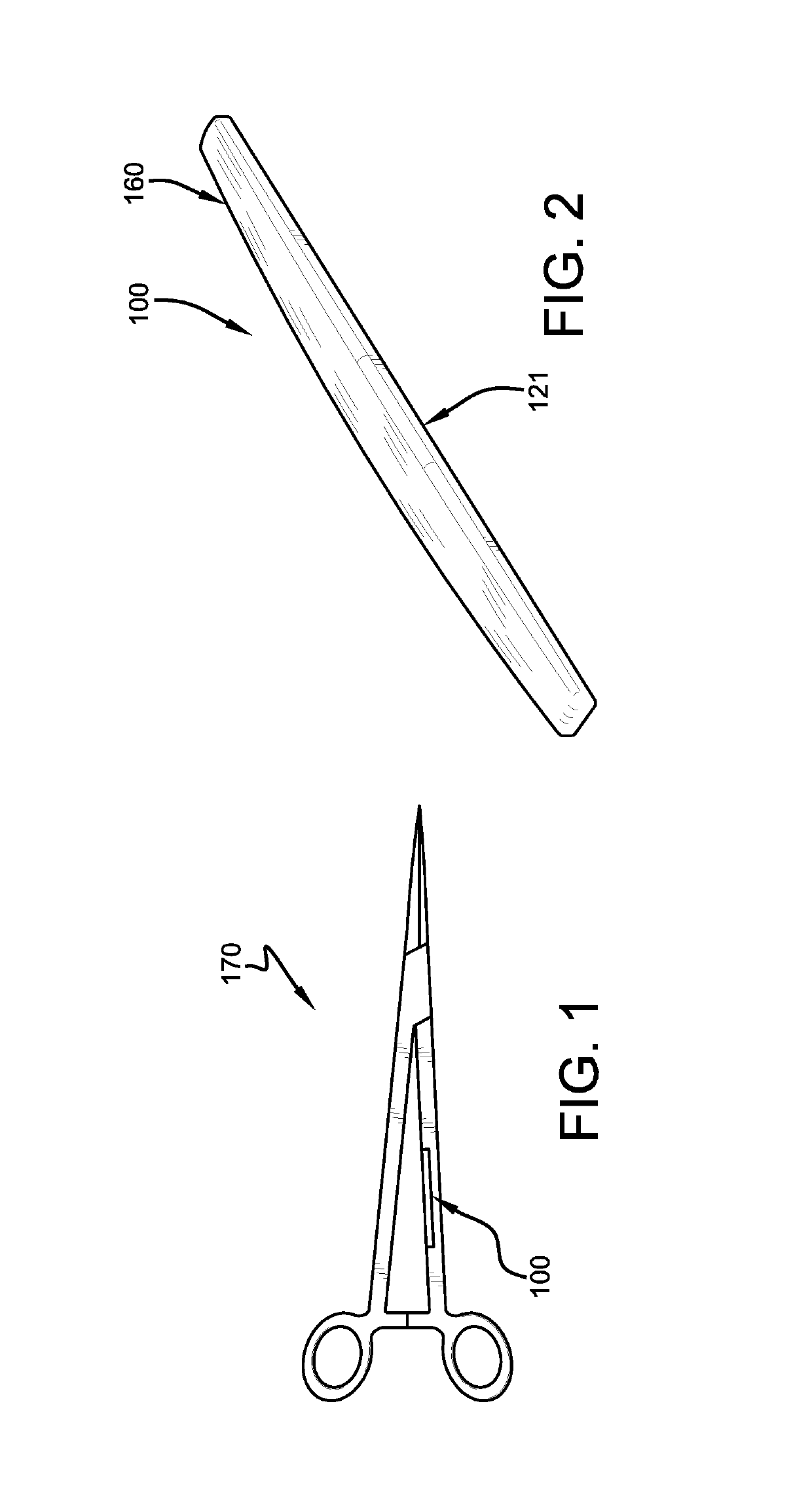
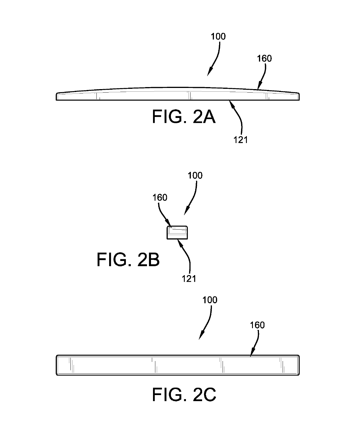
[0034]An article 170, such as a surgical instrument, is illustrated in FIG. 1 with a first exemplary embodiment micro RFID tag 100, according to the subject disclosure, mounted thereon. First exemplary embodiment micro RFID tag 100 includes a substrate assembly 110 (FIGS. 3-5) and an encapsulation layer 160 (FIG. 8) partially or wholly surrounding the substrate assembly. Substrate assembly 110 has a non-conductive support substrate 112 formed from any suitable material, such as fiberglass or other glass epoxy, as is known. Substrate 112 is a single-layer construction and may have a flat printed circuit board (“PCB”) configuration with a longitudinal central axis A. Alternatively, substrate 112 may have a multi-layer construction formed from a suitable process, such that substrate 112 may have multiple integrated circuits and interconnections spanning multiple layers. Substrate 112 generally includes an upper surface 120; elongated, parallel, spaced-apart opposing side edges 114, 116...


PUM


Abstract

A micro radio frequency identification tag for use on articles in an equipment identification and tracking system includes a substrate, an RFID chip, a power storage means, an antenna, and a conductive means. The substrate has a pair of surfaces. The RFID chip and power storage means are operatively retained on one surface. The antenna is operatively retained on the other surface of the substrate and acts as a conductive layer. The conductive means extends between the surfaces of the substrate to operatively connect the antenna to the RFID chip and power storage means.

Description

CROSS-REFERENCE TO RELATED APPLICATION[0001]This application claims the benefit of U.S. Provisional Patent Application Ser. No. 62 / 609,820, filed Dec. 22, 2017.BACKGROUND OF THE INVENTIONField of the Invention[0002]The subject disclosure relates generally to equipment identification and equipment tracking systems. More particularly, the subject disclosure relates to a system for identifying and tracking medical or industrial articles and / or equipment that are exposed to or utilized in extreme environmental conditions. More specifically, the subject disclosure relates to a micro radio frequency identification tag assembly that includes a conductive interface which is operatively mounted to a surgical instrument for identifying and tracking the surgical instrument prior to and following use in the operating room.Background Art[0003]Identification and tracking of articles and other equipment is generally well known. In particular, identification and tracking of articles, such as indust...

Claims


Application Information

Patent Timeline
Patent Type & Authority Patents(United States)
IPC IPC(8): G06K19/077
CPCG06K19/07773G06K19/07722G06K19/00
Inventor BLANK, BRIAN K.
Owner BLANK BRIAN K
Why Eureka
Try Eureka