Transponder and Method for Tuning the Radio Transponder

a radio transponder and transponder technology, applied in the field of radio transponder and radio transponder tuning, can solve the problems of unsuitable passive transponder without a power supply of their own, no possibility of using passive solutions, and adverse reading range effects

Active Publication Date: 2018-07-05
SIEMENS AG
View PDF0 Cites 1 Cited by
  • Summary
  • Abstract
  • Description
  • Claims
  • Application Information

AI Technical Summary

Benefits of technology

[0007]In view of the foregoing, it is therefore an object of the present invention to provide a passively operable radio transponder that is adjustable in a simple manner for use under different ambient conditions, and to provide a suitable method for tuning the radio transponder.

Problems solved by technology

If real ambient conditions differ from those assumed, this generally has an adverse effect on the reading range.
A mismatch is particularly critical in the case of passive transponders, because the absence of a power supply of their own means that there are no compensation options that can keep compensation values.
However, this allows an adjustment to suit varying ambient conditions only rudimentarily.
The design described in US 2010 / 0019907 A1 is therefore unsuitable for passive transponders without a power supply of their own.
As a result, when the varactor diode is used, there is also no possibility to use passive solutions in this.

Method used


Image

  • Transponder and Method for Tuning the Radio Transponder
  • Transponder and Method for Tuning the Radio Transponder
  • Transponder and Method for Tuning the Radio Transponder

Examples


Embodiment Construction

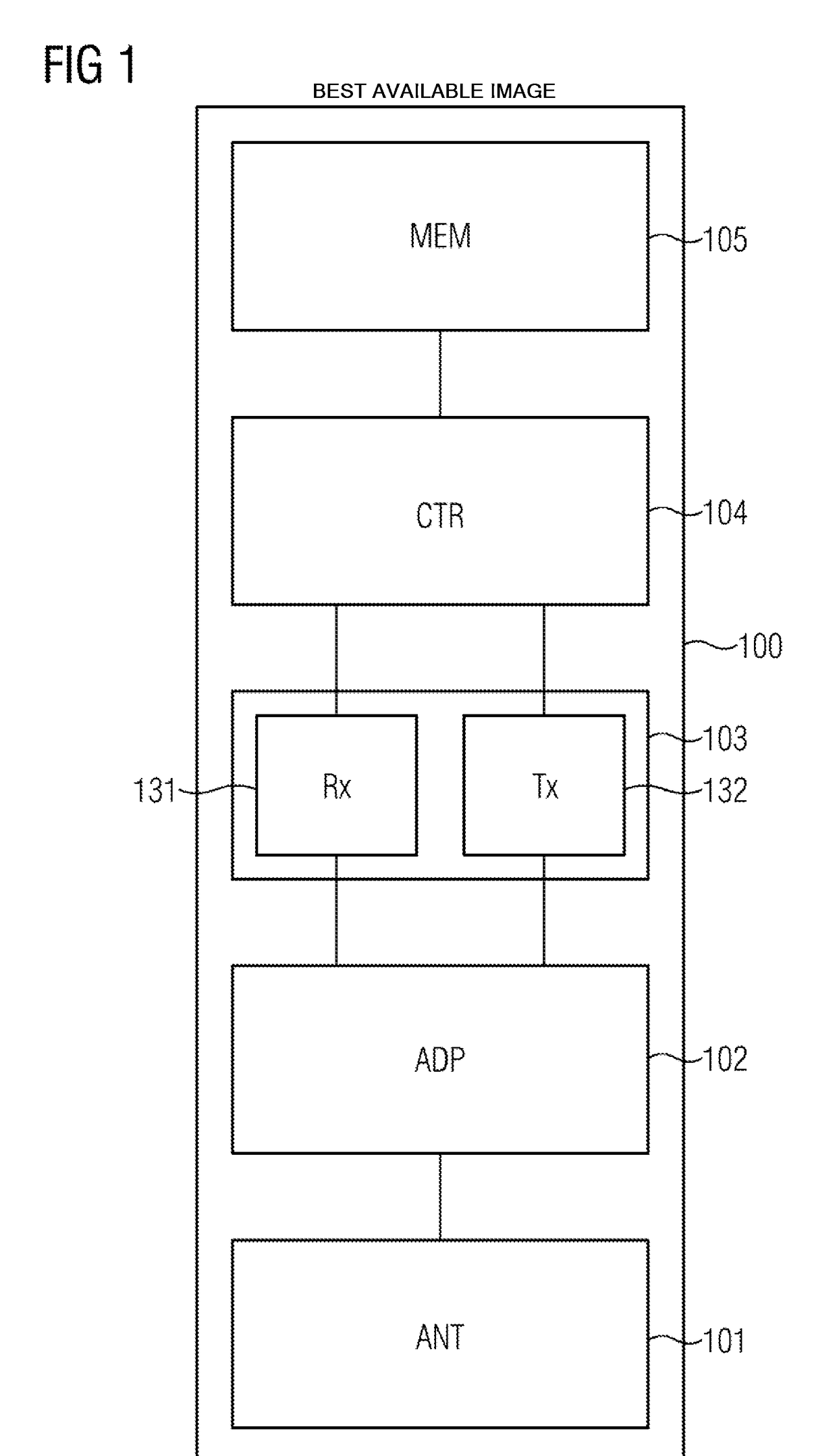
[0020]The radio transponder 100 depicted in FIG. 1 is an RFID tag in the present exemplary embodiment and comprises an antenna 101 and also a transmission and reception unit 103, which has a demodulator unit 131 and a modulator unit 132 for decoding interrogation signals for the radio transponder 100 and for coding response signals from the radio transponder 100.

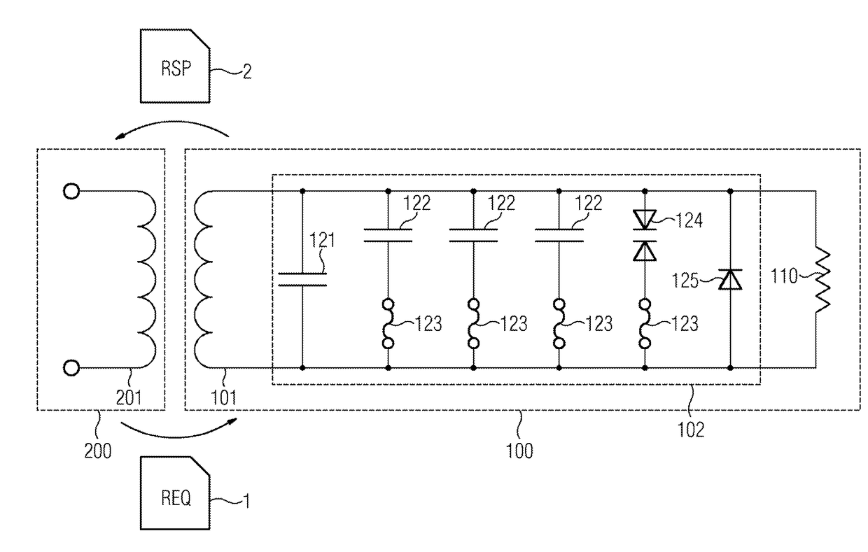
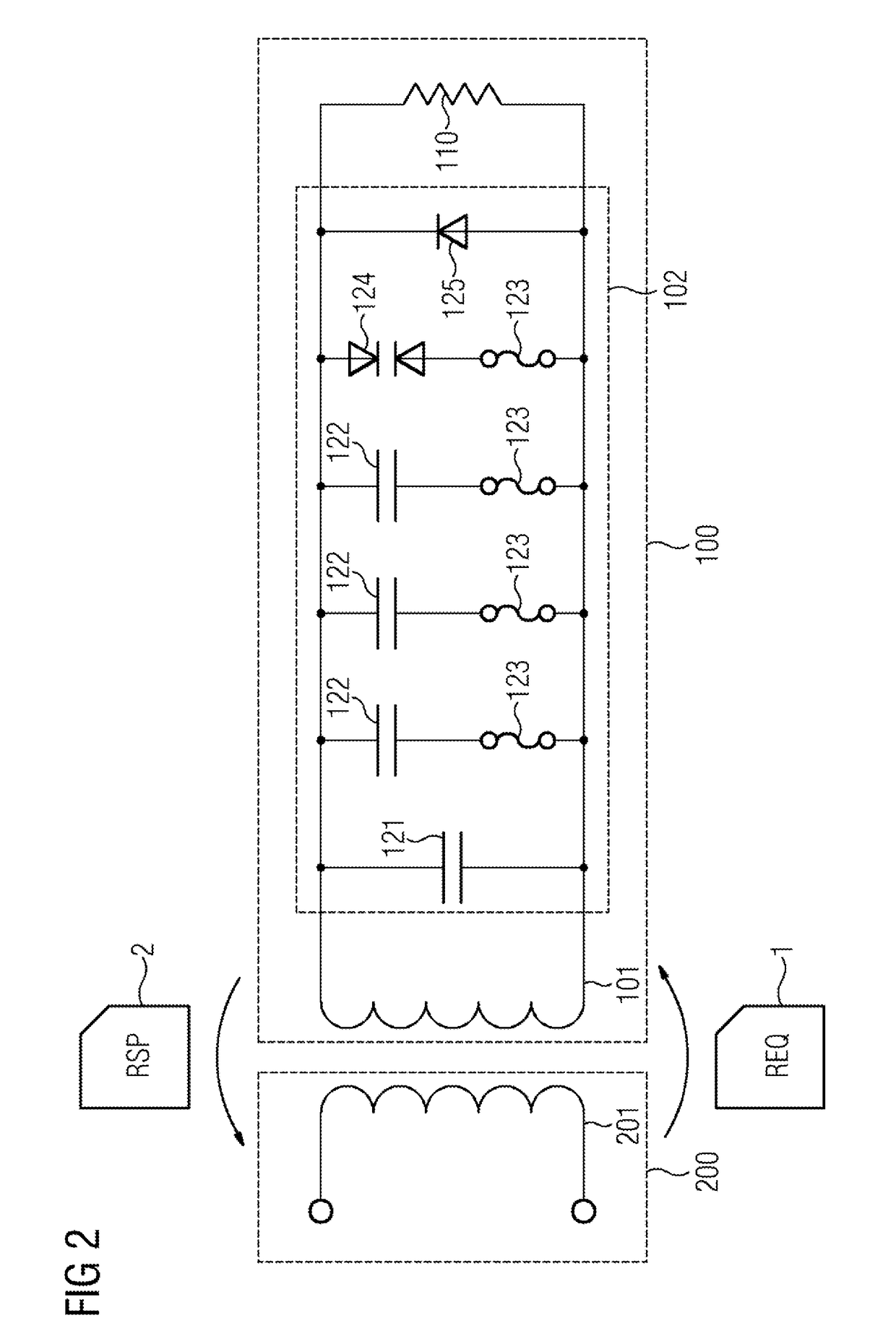
[0021]In accordance with the equivalent circuit diagram depicted in FIG. 2 for a radio transponder system, interrogation signals 1 are preferably transmitted by a radio transponder reader 200 to the radio transponder 100, while response signals 2 are transmitted from the radio transponder 100 to the radio transponder reader 200. The antenna 101 of the radio transponder 100 and an antenna 201 of the radio transponder reader 200 are modelled as intercoupled inductances in the equivalent circuit diagram by way of example. The two antennas can fundamentally also be formed as conventional radiation elements that are in a far fiel...


PUM


Abstract

The invention relates to the tuning of a radio transponder having an antenna, a transceiver unit and a resonant circuit connected to the antenna. The resonant circuit comprises a plurality of capacitors arranged in parallel, each capacitor being arranged in series with a fuse. In this arrangement, a capacitor is switchable by means of a fuse arranged in series for the purpose of tuning the resonant circuit. A control unit associated with the resonant circuit is designed and set up to produce a switching signal for a respective fuse of the resonant circuit on the basis of a control signal transmitted by a radio transponder reader.

Description

CROSS-REFERENCE TO RELATED APPLICATIONS[0001]This is a U.S. national stage of application No. PCT / EP2016 / 063117 filed 9 Jun. 2016 and claims priority of European application No. 15174568 filed Jun. 30, 2015, the content of which is incorporated herein by reference in its entirety.BACKGROUND OF THE INVENTION1. Field of the Invention[0002]The present invention relates to RFID (radio frequency identification) systems and, more particularly, to a radio transponder and method for tuning the radio transponder.2. Description of the Related Art[0003]In (radio frequency identification) (RFID) systems, a maximum reading range and a possible distance between transponder or tag and reader are definitively dependent on a tuning of the transponder for its input resonant circuit. This particularly includes antenna and coil properties. Effective tuning of the input resonant circuit requires the involvement of not only transponder components, such as the housing, but also ambient conditions. Usually...

Claims


Application Information

Patent Timeline
Patent Type & Authority Applications(United States)
IPC IPC(8): G06K19/077H04B1/40H04B17/318G06K19/07
CPCG06K19/07773H04B1/40H04B17/318G06K19/0723G06K19/0709G06K19/0726
Inventor GILA, JANOSJAHN, MARTINSCHIEFER, MARTIN
Owner SIEMENS AG
Why Eureka
Try Eureka