Projection TV

A projection TV and projection technology, applied in the field of projection TV, can solve the problems of difficulty in blocking scattered reflected light and the like

Inactive Publication Date: 2006-10-04
SAMSUNG ELECTRONICS CO LTD
View PDF2 Cites 1 Cited by
  • Summary
  • Abstract
  • Description
  • Claims
  • Application Information

AI Technical Summary

Problems solved by technology

However, although the conventional method for controlling the size of the projection opening or slit can block diffracted light and scattered reflected light generated in the edge region of light, there is a problem in blocking all diffracted light or scattered light generally present in the light flux. Reflecting light is more difficult

Method used


Image

  • Projection TV
  • Projection TV
  • Projection TV

Examples


Embodiment Construction

[0034] Matters such as detailed structures and elements defined in the specification are provided to assist in a comprehensive understanding of the exemplary embodiments of the present invention. Accordingly, those of ordinary skill in the art will recognize that various changes and modifications of the embodiments described herein can be made without departing from the scope and spirit of the invention. Also, descriptions of well-known functions and constructions are omitted for clarity and conciseness.

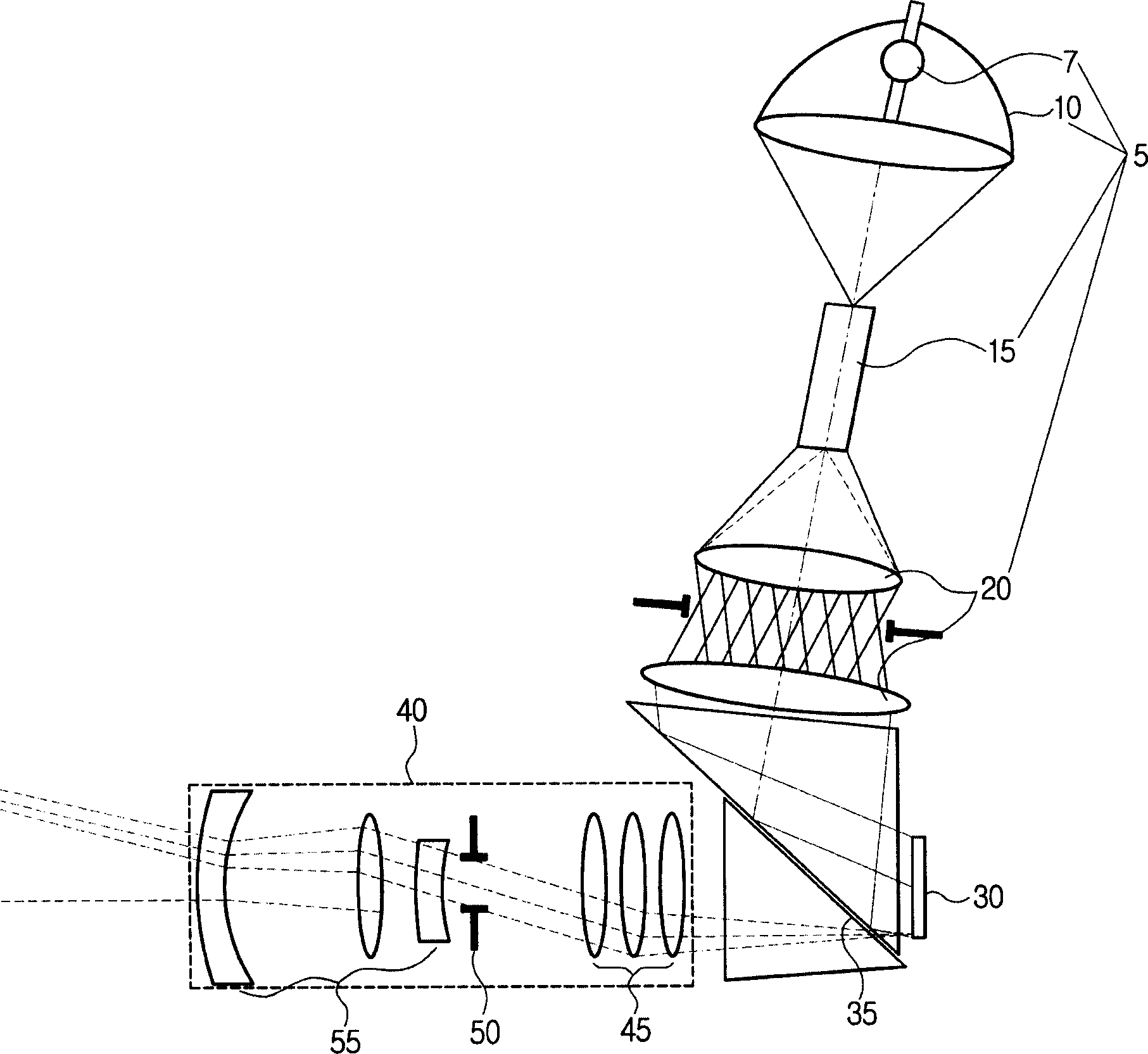
[0035] figure 1is a schematic diagram showing an illumination block and a projection block of a projection television (TV). As shown in the figure, the lighting block 5 includes a lighting lamp 7 , an elliptical reflector 10 , an optical channel 15 , a pair of relay lenses 20 and a reflective plate 35 . The projection block 40 includes a front lens group 45 , a rear lens group 55 and a projection hole 50 . A digital micromirror device (DMD) 30 is provided between the illu...


PUM


Abstract

Provided is a projection television TV having a digital micro mirror device (DMD) which includes micro-mirrors to reflect light from a light source according to an 'on' or 'off' state of the micro mirrors. An illuminating block provides light to the DMD in a uniform optical intensity. A projecting block projects the light reflected from the DMD onto a screen. The projection TV features a projection aperture positioned in the projecting block or the illuminating block arranged perpendicularly to an optical axis. The projection aperture forms an optical path and includes projection areas to pass the light and blocking areas to block the light. The projection area and the blocking area are formed on a cross section of the light with a predetermined space.

Description

technical field [0001] The present invention relates to a projection television (TV). More particularly, the present invention relates to a projection television that improves image clarity and contrast by removing diffracted light and scattered reflected light contained in light from a light source. Background technique [0002] In general, projection televisions (TVs) embody images on a large screen by forming images in image forming devices such as cathode ray tubes (CRTs) and liquid crystal displays (LCDs). Projection TV projects images on a large screen through lighting blocks, projection blocks and mirrors. [0003] figure 1 is a schematic diagram showing an illumination block and a projection block of a projection TV. The projection TV includes a digital micromirror device (DMD) 30 for projecting images, an illumination block, and a projection block. The lighting block 5 includes a lighting lamp 7 , an elliptical reflector 10 , an opti...

Claims


Application Information

Patent Timeline
Patent Type & Authority Applications(China)
IPC IPC(8): H04N5/74
CPCH04N9/3197H04N9/3141H04N5/7458H04N5/74
Inventor 李钟洙赵虔皓可里尔·索克洛夫鲍尔多赖·亚历克塞
Owner SAMSUNG ELECTRONICS CO LTD
Why Eureka
Try Eureka