Optical rotating bench

A rotating table and optical technology, which is applied in the direction of optics, optical components, optical instrument testing, etc., can solve the problems of heavy weight, bulky, complex structure design of optical rotating table, etc., and achieve the effect of heavy weight and large volume

Inactive Publication Date: 2006-10-11
SHANGHAI INST OF OPTICS & FINE MECHANICS CHINESE ACAD OF SCI
View PDF0 Cites 4 Cited by
  • Summary
  • Abstract
  • Description
  • Claims
  • Application Information

AI Technical Summary

Problems solved by technology

[0006] In the two optical rotary tables described in the prior art [2] and [3], since the two rotary tables and optical components are directly supported by the rotating shaft system, in order to

Method used


Image

  • Optical rotating bench
  • Optical rotating bench
  • Optical rotating bench

Examples


Embodiment Construction

[0032] The optical rotary table of the present invention will be further described below in conjunction with the accompanying drawings and embodiments, but this should not limit the protection scope of the present invention.

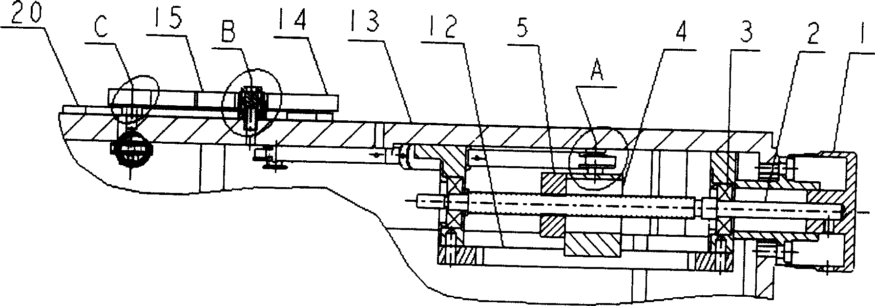
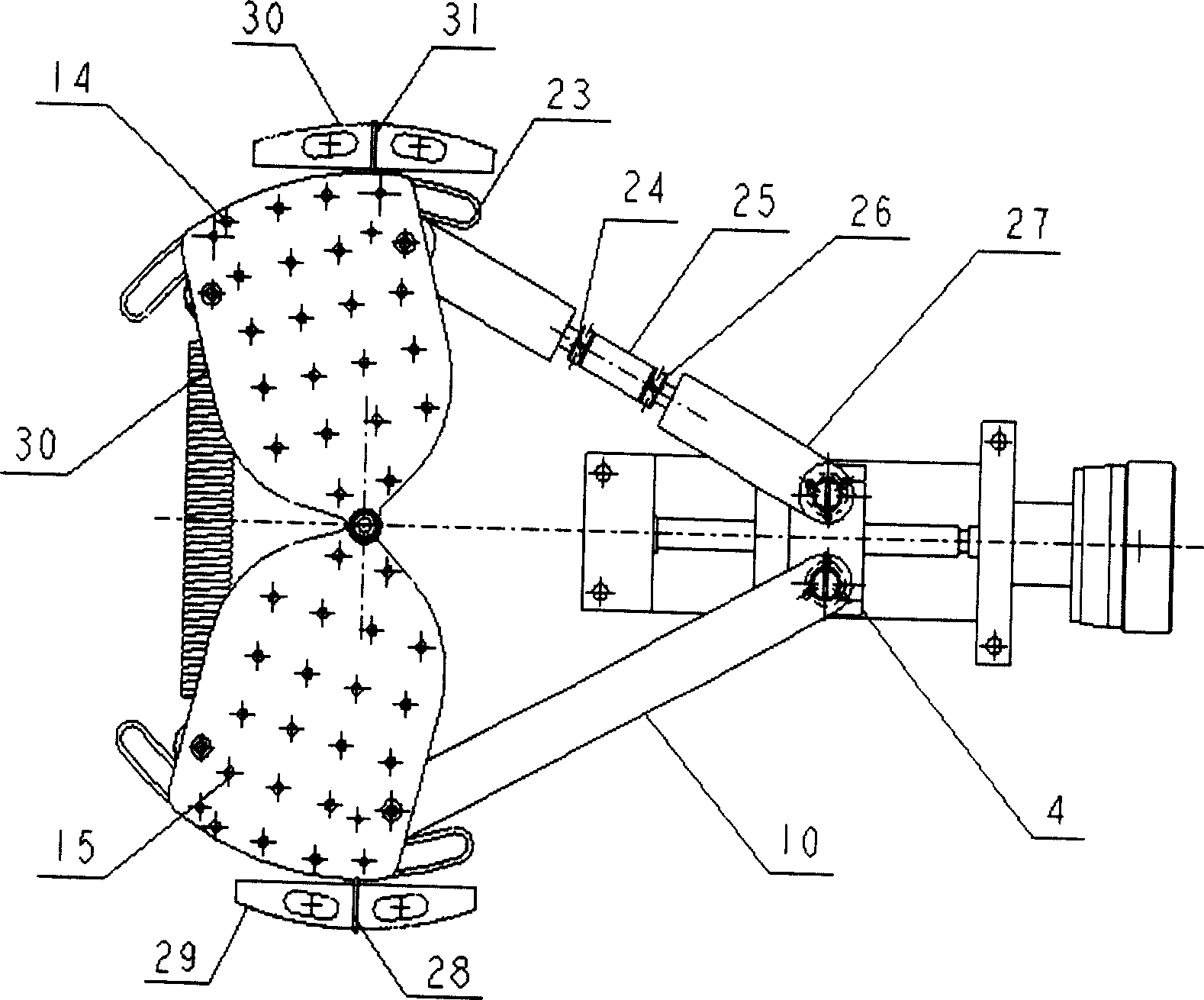
[0033] see first figure 1 with figure 2 , figure 1 is a front view of an embodiment of the optical turntable of the present invention, figure 2 yes figure 1The top view of the base 13 of the optical turntable when it is in default. It can be seen from the figure that the optical turntable of the present invention includes a base 13, the optical turntable is a left-right symmetrical structure, a drive source 1 is fixedly connected with the ball screw 2, and the two ends of the ball screw 2 are respectively equipped with a second A bearing 3 is matched with the first nut 5 in the middle, and a slider 4 is fixed on the nut 5. The boss on the slider 4 is matched with the groove in a guide plate 12, and the guide plate 12 is fixed Below the base 13, on...


PUM


Abstract

The invention discloses an optical rotary table, which is formed by a driving source, a roller lead screw, a nut, a sliding block, a guide plate, a connecting rod, a middle post, a bearing, a plate, a base, a roller sheath, a rolling guide rail, a tension spring, a read block and a pointer. Wherein, said optical rotary table is left and right symmetry; the connecting rod, plate, roller guide rail, roller, roller sheath, read block and point are both distributed one group at the left and right of symmetry line. The invention has simple structure and easy installment, while two groups of optical elements rotate coaxially in reversed directions synchronously and the rotate angle difference can be accurately adjusted.

Description

technical field [0001] The invention relates to an optical rotary table, in particular to an optical rotary table suitable for two groups of optical components to rotate synchronously and reversely around a common axis, and the rotation angle difference can be adjusted in a small amount. Background technique [0002] The optical rotary table is a common adjustment device for adjusting the angle of optical components in optical experiments and optical instruments. The optical components are fixed on the platen of the optical turntable, and their angles can be adjusted by the rotation of the optical turntable. [0003] The prior art [1] (the Newport Resource, Motion Control: Manual Rotation Stages and Motorized Rotation Stages. 2003, P.969-1032) describes various models of one-dimensional optical rotation stages. These one-dimensional optical turntables are widely used because of their individuality and diversity, meeting many requirements for use. But a one-dimensional opti...

Claims


Application Information

Patent Timeline
IPC IPC(8): G02B27/62G01M11/04
Inventor 王利娟刘立人朱宝钤栾竹刘德安周煜
Owner SHANGHAI INST OF OPTICS & FINE MECHANICS CHINESE ACAD OF SCI
Why Eureka
Try Eureka