Device using magnetic field wave pattern as transmission signal

A signal and magnetic wave technology, applied in the field of devices that use magnetic field waveforms as transmission signals, can solve the problems of limited transmission range, inability to have both, and high cost.

Inactive Publication Date: 2006-10-11
骆俊光
View PDF0 Cites 1 Cited by
  • Summary
  • Abstract
  • Description
  • Claims
  • Application Information

AI Technical Summary

Problems solved by technology

[0003] The existing wired connection method mainly uses cables to extend the connection, and then cooperates with signal improvement devices such as boosters to improve the quality of receiving signals. However, using wired optical fiber cables for transmission is expensive and expensive. It is bound to be passed on to consumers, so this is why consumers still have to pay for expensive wired communication reception fees
[0004] The existing wireless connection method mainly uses the power line for carrier transmission, but it is limited to a limited area of ​​a power supply meter, that is, within the area of ​​the power supply meter, signals can be made wirelessly Transmission / reception enables information exchange between hardware and hardware. However, because the meter has a built-in transformer, the coupling coil of the transformer will block the carrier signal. Therefore, when the signal reaches the coupling coil, it will be blocked immediately. Therefore, wireless communication The use is limited to a fixed area within the power supply meter, and can no longer be transmitted outside the power supply meter, so the use efficiency of wireless communication is low
[0005] Therefore, the existing wired communication method has the disadvantage of high cost, while the existing wireless communication method is limited by the barrier factor of the transformer supplying the ammeter, and the transmission range is limited. the solution

Method used


Image

  • Device using magnetic field wave pattern as transmission signal
  • Device using magnetic field wave pattern as transmission signal

Examples


Embodiment Construction

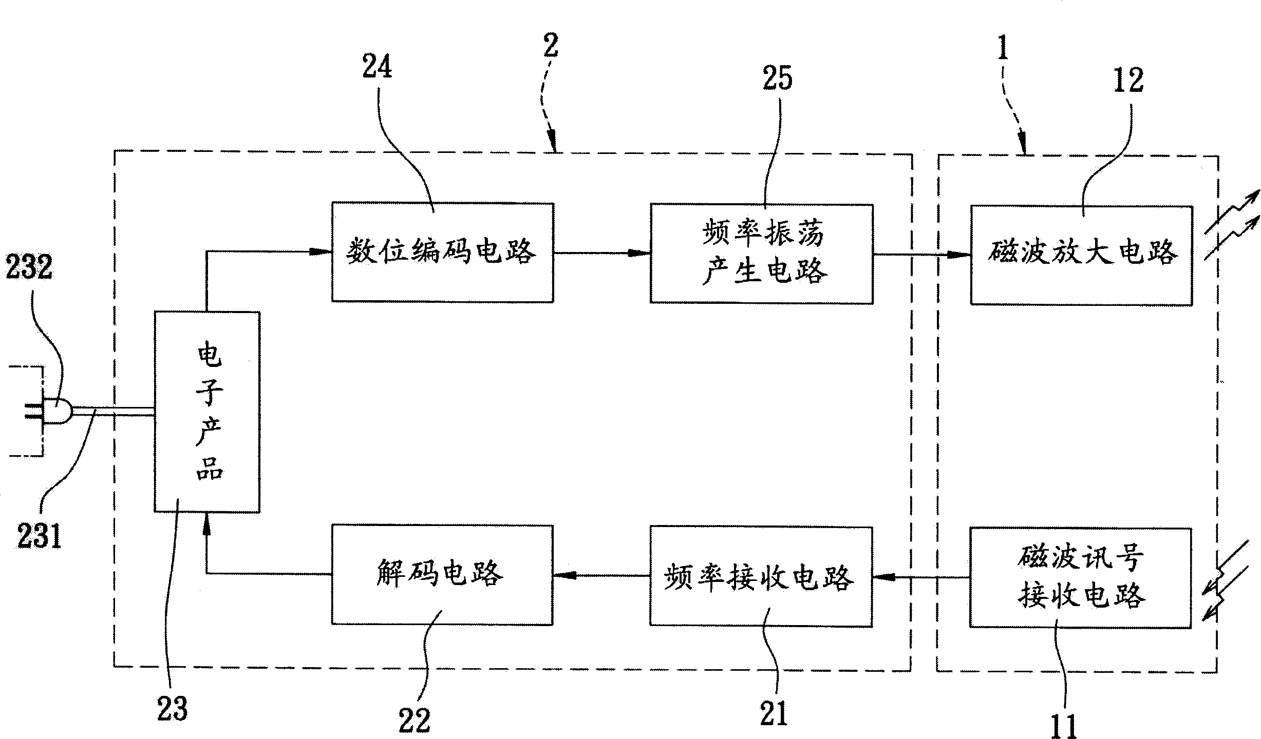
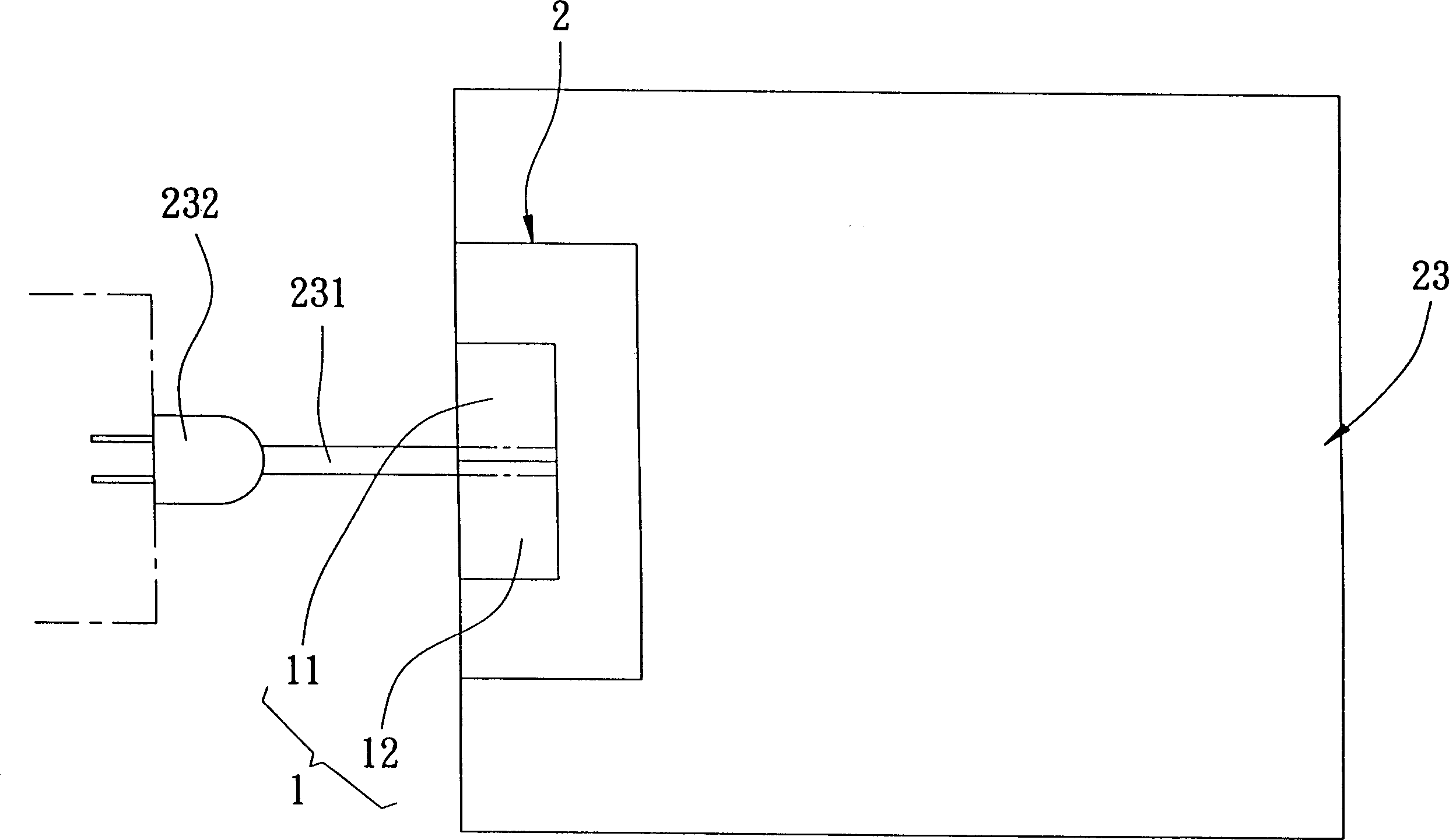
[0014] refer to figure 1 and figure 2 , the preferred embodiment of the device using the magnetic field waveform as the transmission signal of the present invention includes a magnetic wave control device 1 and a main control device 2 .

[0015] The magnetic wave control device 1 has a magnetic wave signal receiving circuit 11 for receiving external frequency signals, and a magnetic wave amplifying circuit 12 for amplifying the frequency signals.

[0016] The main control device 2 is electrically connected between the magnetic wave signal receiving circuit 11 and the magnetic wave amplifying circuit 12. The main control device 2 has a frequency receiving circuit 21, a decoding circuit 22, an electronic product 23, and a digital encoding circuit 24. And a frequency oscillation generating circuit 25. In this example, the electronic product 23 is a computer.

[0017] As for the wireless signal transmission device of the present invention, when the electronic product 23 uses a...


PUM


Abstract

The device with magnetic waveform as transmission signal comprises a magnetic wave controller with a magnetic wave signal receiving circuit and an amplifying circuit, and a master controller connected between former receiving and amplifying circuits and composed in turn by a frequency receiving circuit, a decoding circuit, an electric product, a digital coding circuit, and a frequency oscillation generating circuit.

Description

technical field [0001] The present invention relates to a device using power as a communication device, in particular to a device using a magnetic field waveform as a transmission signal. Background technique [0002] Existing home appliance communication systems, such as cable television, computers, local telephones, etc., are divided into "wired connection" and "wireless connection" in order to connect remote signals. [0003] The existing wired connection method mainly uses cables to extend the connection, and then cooperates with signal improvement devices such as boosters to improve the receiving quality. However, using wired optical fiber cables for transmission is expensive and expensive. It is bound to be passed on to consumers, so this is why consumers still have to bear the cost of receiving expensive wired communications. [0004] The existing wireless connection method mainly uses the power line for carrier transmission, but it is limited to a limited area of ​​...

Claims


Application Information

Patent Timeline
Patent Type & Authority Applications(China)
IPC IPC(8): H04B7/00
Inventor 骆俊光
Owner 骆俊光
Why Eureka
Try Eureka