Engine fuel feed device

A fuel supply device and fuel supply technology, applied in the direction of engine components, combustion engines, machines/engines, etc., can solve the problems of pressure rise, accumulation in the tank, internal temperature rise, etc., easy to achieve output control, avoid excessive rise, Avoid the effect of gasification

Inactive Publication Date: 2006-10-18
NIKKI CO LTD
View PDF3 Cites 5 Cited by
  • Summary
  • Abstract
  • Description
  • Claims
  • Application Information

AI Technical Summary

Problems solved by technology

[0007] However, since this technology only controls the fuel discharge amount and the switching of the fuel supply method according to the temperature of the engine fuel system parts, it is not a method to minimize the return fuel to the fuel tank while avoiding vaporization of the supplied fuel. Therefore, during idling of taxi vehicles, etc., which are assumed to be heated from the engine for a long time, return fuel with a high temperature for a long time is accumulated in the tank, causing a problem that the internal temperature rises excessively and the pressure also rises at the same time.

Method used


Image

  • Engine fuel feed device
  • Engine fuel feed device
  • Engine fuel feed device

Examples


Embodiment Construction

[0029] The embodiments of the present invention will be described in detail below with the accompanying drawings.

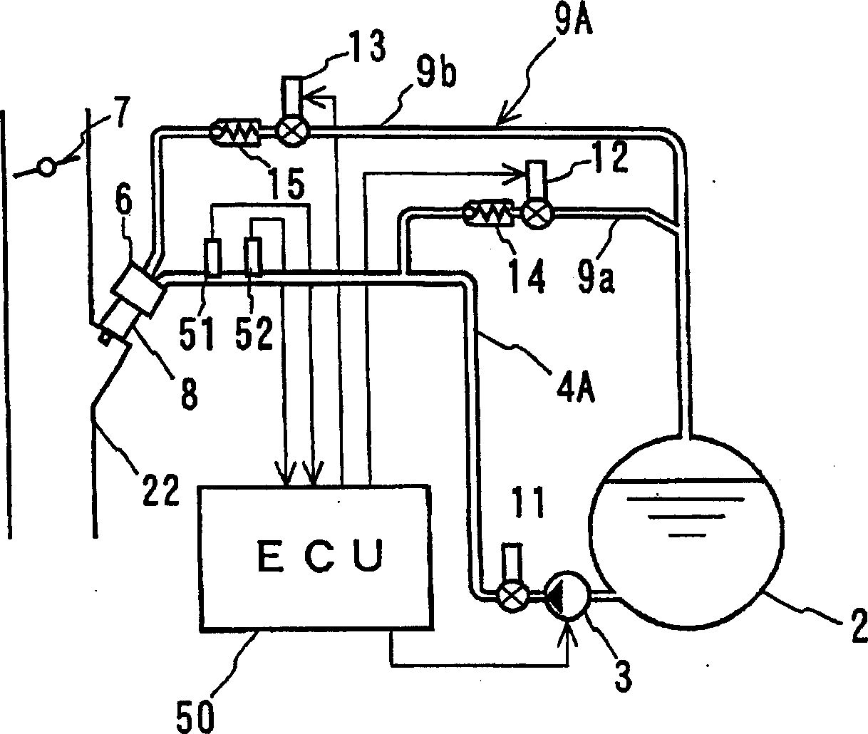
[0030] figure 1 Shows the layout of the fuel supply system of the engine equipped with the fuel supply device of this embodiment. The fuel pump 3 is arranged on the outlet side of the fuel tank 2, and the fuel supply line 4A is in the intake pipe 22 of the engine not shown. The middle part is arranged downstream of the throttle valve 7 and connected to a fuel guide 6 in which a plurality of injectors 8 are arranged.

[0031] In addition, in the fuel supply line 4A near the fuel tank 2 (for example, in the rear cargo tank of the vehicle, etc.), the first fuel return line 9a that is branched here and connected to the fuel tank 2 has a check valve 14 and Block valve 12. In addition, the second fuel return line 9b that extends from the tip side of the fuel guide 6 and merges on the downstream side of the shutoff valve 12 of the first fuel return line 9a has a check val...


PUM


Abstract

PROBLEM TO BE SOLVED: To provide an engine fuel supply device that changes over a liquefied gas fuel supply system between a return mode and a returnless mode, avoiding excessive temperature rise in a fuel tank by controlling return fuel to be minimized while surely avoiding the vaporization of supply fuel. SOLUTION: The engine fuel supply device comprises a first fuel return pipeline 9a branching on the way of a fuel supply pipeline and a second fuel return pipeline 9b for returning fuel, not injected by an injector 8, both of which have shut-off valves 14, 15, respectively, and are connected to a fuel tank 2. A fuel pressure sensor 52 and a fuel temperature sensor 51 are arranged in the fuel supply pipeline near the injector 8 and a fuel rail 6. An electronic control unit 50 for detecting their output signals executes control into the return mode when determining that injected fuel may be in a vaporized condition and at starting the engine and into the returnless mode during normal operation. COPYRIGHT: (C)2007,JPO&INPIT

Description

Technical field [0001] The present invention relates to a fuel supply device that injects liquid fuel that is easily vaporized compared to gasoline like LPG or DME into an intake pipe from an injection valve and supplies it to an engine, and more particularly to a fuel supply device for such an engine: The LPG in the supply line is vaporized and injected in a stable liquid state to avoid excessive temperature rise in the fuel tank. Background technique [0002] A system for metering and injecting liquid fuel in a liquid manner with an injection valve arranged in the intake pipe and supplying it to the engine is well known, but for gasoline, such as Figure 6 As shown, the liquid fuel stored in the fuel tank 2 is pressurized by the pump 3, sent to the fuel guide 6 by the fuel supply line 4B, and then distributed to the injection valve 8 arranged in the intake pipe 22 of the engine 21 The remaining fuel that has not been injected is returned to the fuel tank 2 via the fuel return l...

Claims


Application Information

Patent Timeline
Patent Type & Authority Applications(China)
IPC IPC(8): F02M37/08F02M37/20
CPCY02T10/12Y02T10/30
Inventor 山口真也津坂智田沼正义布川刚史稻生州俊
Owner NIKKI CO LTD
Why Eureka
Try Eureka