Heat exchanger

A technology of heat exchangers and heat exchange tubes, applied in heat exchange equipment, heat exchanger shells, lighting and heating equipment, etc., which can solve the damage of evaporator refrigeration performance, identify refrigerant flow holes, and cannot obtain refrigerant, etc. problem, to achieve the effect of reduced quantity, uniform quantity and high heat exchange performance

Inactive Publication Date: 2006-10-18
SHOWA DENKO KK
View PDF1 Cites 37 Cited by
  • Summary
  • Abstract
  • Description
  • Claims
  • Application Information

AI Technical Summary

Problems solved by technology

[0010] However, since the position of the refrigerant passage hole cannot be recognized from the outside when the assembly is assembled to manufacture the evaporator, it is possible to longitudinally incorporate the resistance plate into the assembly

Method used


Image

  • Heat exchanger
  • Heat exchanger
  • Heat exchanger

Examples


Embodiment Construction

[0065] Embodiments of the present invention will be described below with reference to the drawings. These examples are evaporators according to the invention.

[0066] In the instructions below, figure 1 and 10 The upper and lower parts, and the left-hand and right-hand sides, are referred to as "upper," "lower," "left," and "right," respectively. In addition, in the following description, the term "aluminum" includes aluminum alloys in addition to pure aluminum.

[0067] In the drawings, the same components will be denoted by the same reference numerals and description will not be repeated.

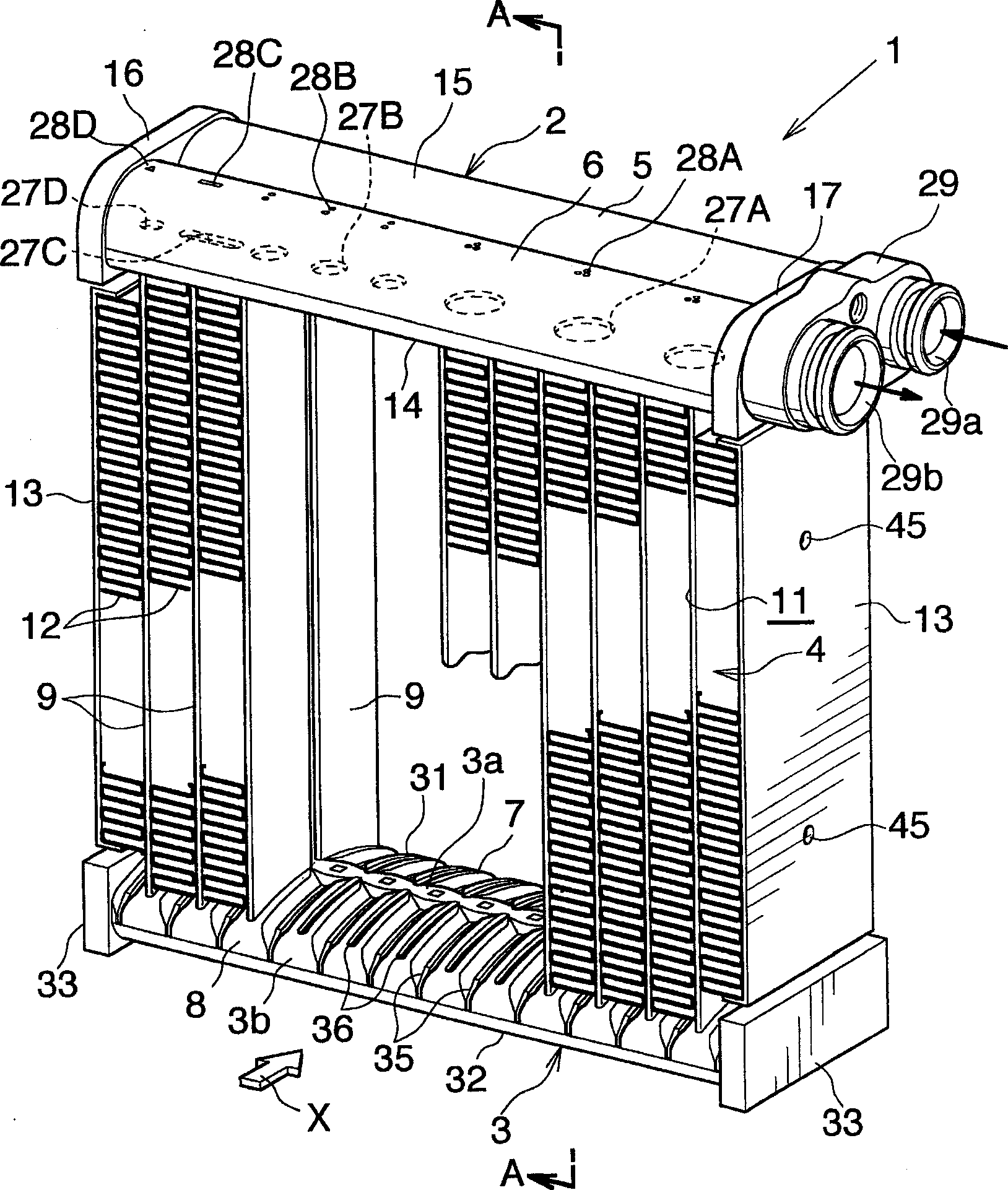
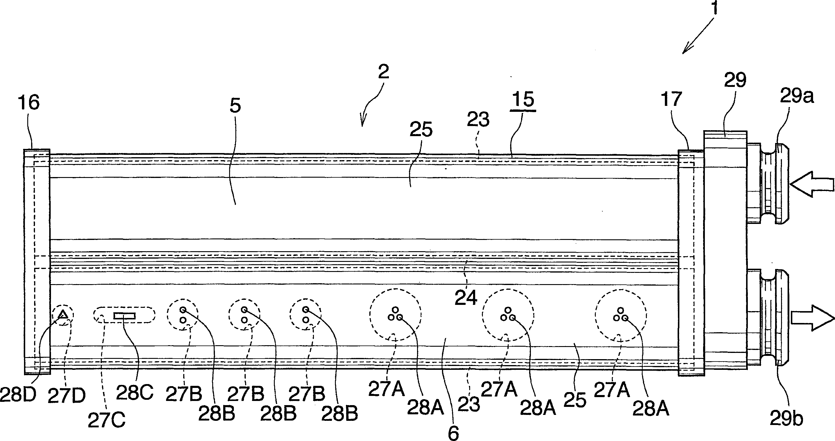
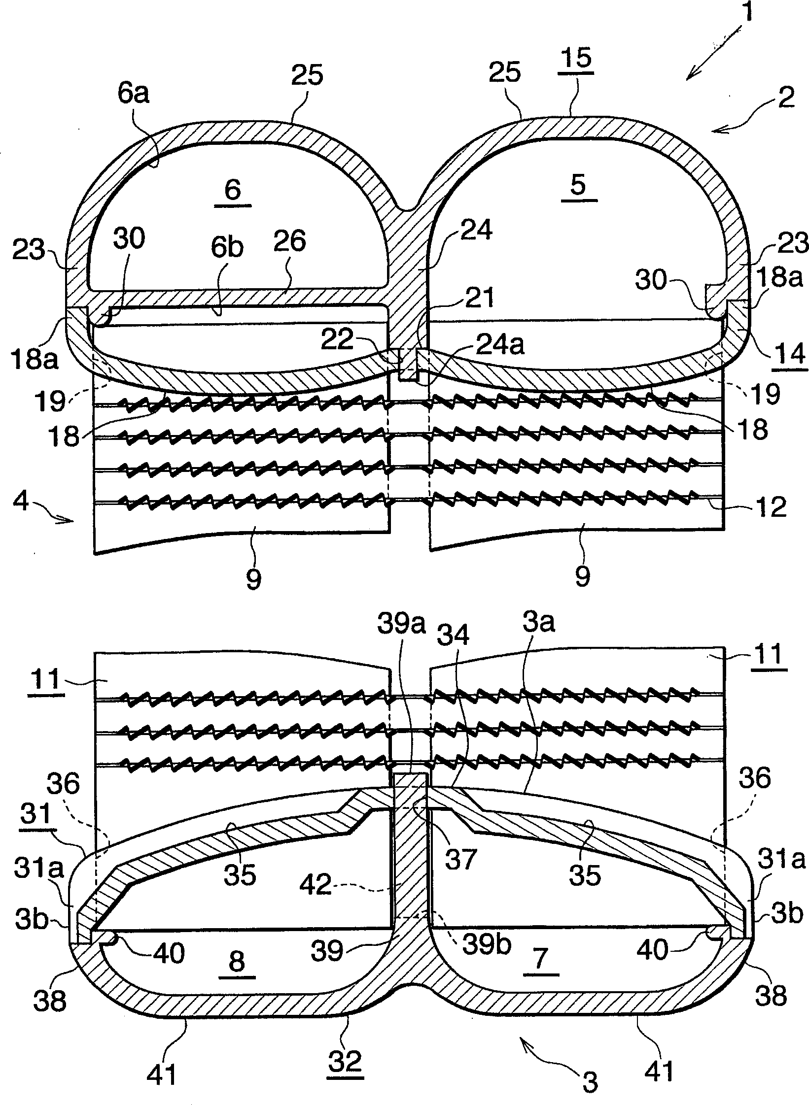
[0068] Figures 1 to 3 The overall structure of the first embodiment of the evaporator according to the present invention is shown, and FIGS. 4 to 7 show the structure of main parts. Figure 8 shows the method of assembling heat exchange tubes, fins and side plates to make an evaporator, while Figure 9 Shows the flow of refrigerant through the evaporator.

[0069] figure 1 Shown...


PUM


Abstract

A heat exchanger (1), comprising: a heat exchange core (4) composed of a plurality of heat exchange tubes (9), a refrigerant inlet header (5) arranged toward one end of each heat exchange tube, and a refrigeration A refrigerant outlet header (6), and a refrigerant inflow header (7) and a refrigerant outflow header (8) disposed toward the other end of each heat exchange tube. The interior of the outlet header on which some of the heat exchange tubes are joined to communicate with the space (6b) is divided into two spaces (6a, 6b) by a flow-dividing resistance plate (26). A plurality of refrigerant circulation holes (27A-27D) having different shapes and/or sizes are formed in the resistance plate (26). The outlet headers have markings (28A-28D) on the outer surface for identifying the location of the refrigerant flow holes (27A-27D) and representing the shape and/or size of said holes. The heat exchanger exhibits high heat exchange performance when used as an evaporator.

Description

[0001] Cross References to Related Applications [0002] This application was filed pursuant to 35 U.S.C. §111(a) and was filed under 35 U.S.C. §119(e)(1) on August 25, 2003 and March 24, 2004, respectively, under 35 U.S.C. §111(b) ) filing date benefits of provisional applications No. 60 / 497338 and No. 60 / 555706 filed. technical field [0003] The invention relates to a heat exchanger, in particular to a heat exchanger used as an evaporator in a motor vehicle air conditioner, ie a refrigeration cycle installed in a motor vehicle. [0004] The downstream side of the air to pass through the airflow gap between each pair of adjacent heat exchange tubes ( figure 1 and 10 the direction indicated by the arrow X, and image 3 and 11 The right-hand side of ) is referred to herein and in the appended claims as "front" and the opposite side is referred to as "rear". Background technique [0005] Hitherto, so-called stacked-plate evaporators are widely used as motor vehicle evapo...

Claims


Application Information

Patent Timeline
IPC IPC(8): F28F9/22
Inventor 渡边宽彦有野康太
Owner SHOWA DENKO KK
Why Eureka
Try Eureka