Motor lock

A technology of motor locks and micro-motors, applied in the field of motor locks, can solve problems such as damage to locks

Inactive Publication Date: 2006-10-25
周项觉
View PDF1 Cites 4 Cited by
  • Summary
  • Abstract
  • Description
  • Claims
  • Application Information

AI Technical Summary

Problems solved by technology

[0003] The main defects of existing motor locks are: due to the use of electronic control circuits to control the motor, when the power fails, the door can be manually opened and then closed and cannot be...

Method used


Image

  • Motor lock
  • Motor lock
  • Motor lock

Examples


Embodiment Construction

[0009] The present invention will be further described below in conjunction with the embodiments and accompanying drawings.

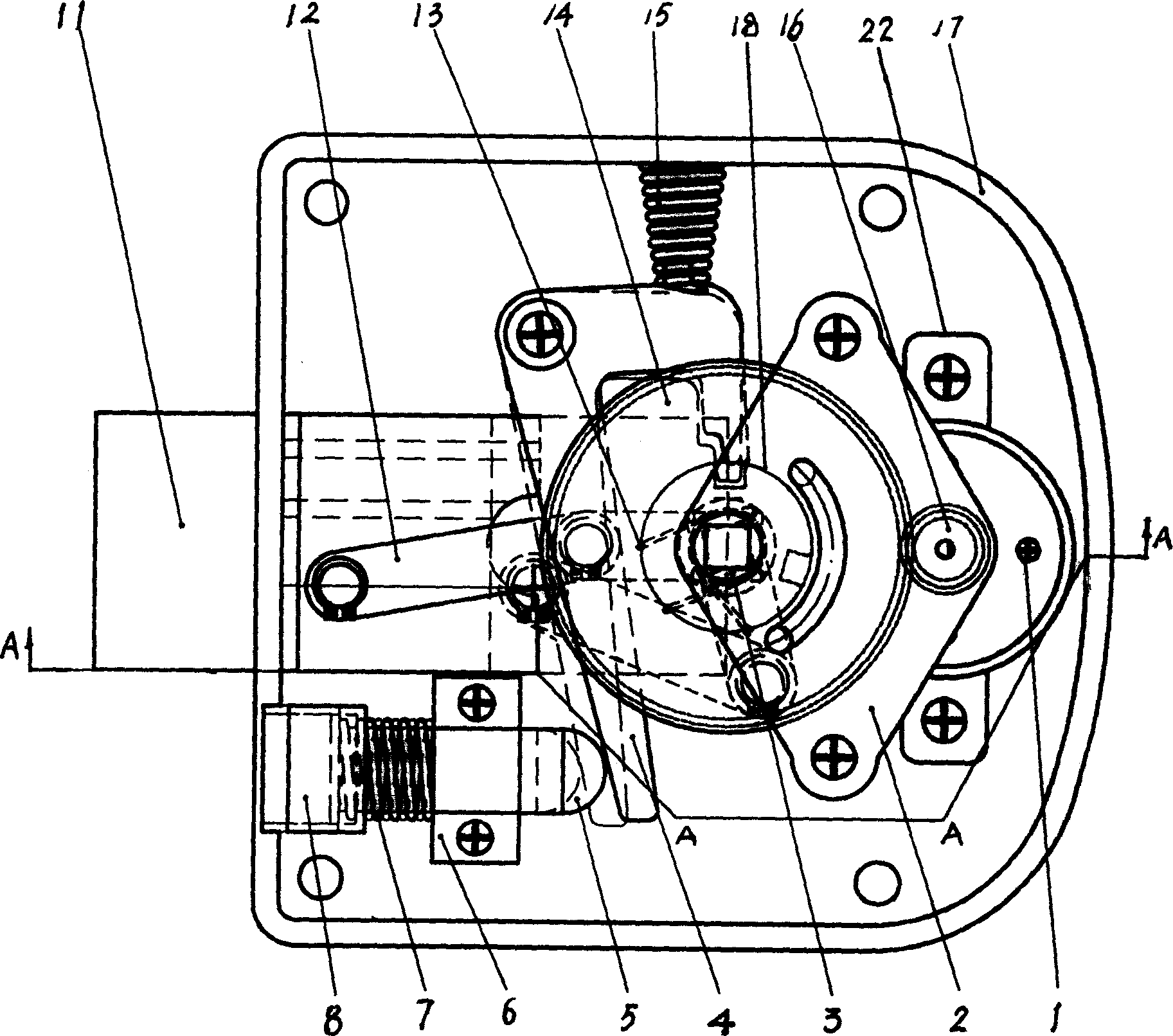
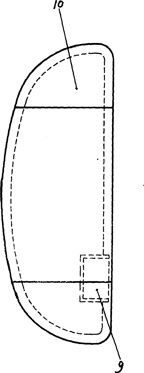
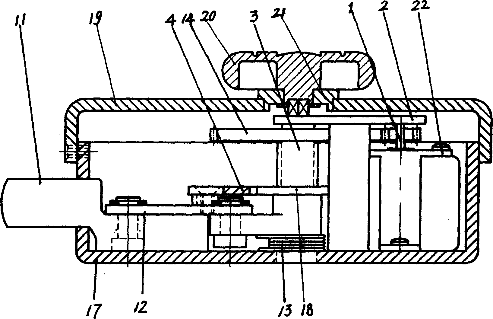
[0010] see Figure 1-Figure 3 , a kind of motor lock, including lock body and buckle 10, deadbolt 11, key, knob 20, micro-motor 1, lock body is constituted by main housing 17 and cover 19, and knob 20 passes through cover 19 and its shaft extends into the lock body, the micromotor 1 is installed in the main casing 17, the pinion 16 is installed on the extension shaft of the micromotor 1, the positioning plate 2 is fixed on the main casing 17, one end of the pulling rod rotating shaft 3 is sleeved in the main casing 17 and the other The positioning plate 2 fitted at one end can be rotated, the large gear 14 is set on the puller shaft 3, the large gear 14 meshes with the pinion 16, one end of the connecting rod 12 is connected with the puller shaft 3 and the other end is connected with the lock tongue 11, and the turntable 18 is set in the puller shaft 3...


PUM


Abstract

The invention is an electric machine lock, comprising lock body, lock latch, lock tongue, key, knob and micromotor, where the lock body is composed of main casing and cover, the knob passes through the cover and the shaft of the knob extends into the lock body, and it is driven by the micromotor, a small gear drives a large gear, a pull rod rotating shaft drives a link rod, the link rod drives the lock tongue back, a fastening plate is inserted into a special-set groove on a rotating disc under the action of a pagoda spring to fasten the rotating disc so as to achieve the door-opening purpose; a magnetic steel A is fastened in the step inner hole of the push rod, a magnetic steel B is fixed in the lock latch to be opposite to the center of the magnetic steel A and the same polarities are opposite, and under the action of repulsive force, the push rod is driven to trigger the fastening plate to shrink the pagoda spring; the fastening plate is drawn out from the special-set groove and the door is automatically locked under the action of torsional spring. Whether the power is cutoff or not, closing the door can implement automatic locking of the door, and the lock tongue can not be drawn out, manually or electrically.

Description

1. Technical field [0001] The invention relates to the field of locks, in particular to a motor lock which uses a micro-motor to open and close the lock. 2. Background technology [0002] Existing motor locks all adopt reed switches and circuit boards to control motors, such as a "new motor lock" disclosed by a Chinese patent (ZL02259181.8, date of announcement: 2003.12.10), which includes a main lock body and a secondary lock body that is Lock buckle, lock head assembly and three-eye plate, key, knob, control circuit board and electronic control circuit, micro-motor, the main lock body is composed of the main lock shell and the main lock cover, and the knob passes through the main lock cover and its shaft extends into The main lock body is equipped with a micro-motor and a control circuit board. The electronic control circuit controls the positive and negative rotation of the micro-motor. It is characterized in that the positive and negative rotati...

Claims


Application Information

Patent Timeline
IPC IPC(8): E05B47/02
Inventor 周项觉
Owner 周项觉
Why Eureka
Try Eureka