Flow-field board of fuel cell

A fuel cell and flow field plate technology, which is applied to fuel cells, fuel cell components, fuel cell additives, etc., can solve the problems of difficult proton conduction and easy occurrence of water in the front section of the diversion groove, and improve the stability. and reliability, preventing water accumulation, and improving drainage capacity

Inactive Publication Date: 2006-10-25
BYD CO LTD
View PDF0 Cites 10 Cited by
  • Summary
  • Abstract
  • Description
  • Claims
  • Application Information

AI Technical Summary

Problems solved by technology

[0010] The purpose of the present invention is to overcome the disadvantages of the existing fuel cell, the proton conduction in the front section of the diversion groove on the flow field plate is difficult, and the back section is prone to water accumulation, and to provide a proton conduction in the front section of the diversion groove is easy, and the rear section is not easy Flow field plate of a fuel cell with water accumulation

Method used


Image

  • Flow-field board of fuel cell
  • Flow-field board of fuel cell
  • Flow-field board of fuel cell

Examples


Embodiment 1

[0039] This embodiment provides a fuel cell flow field plate in which the number and depth of the flow guide grooves are constant but the width of the flow guide grooves is changed. The width of the flow guide groove on the flow field plate changes linearly.

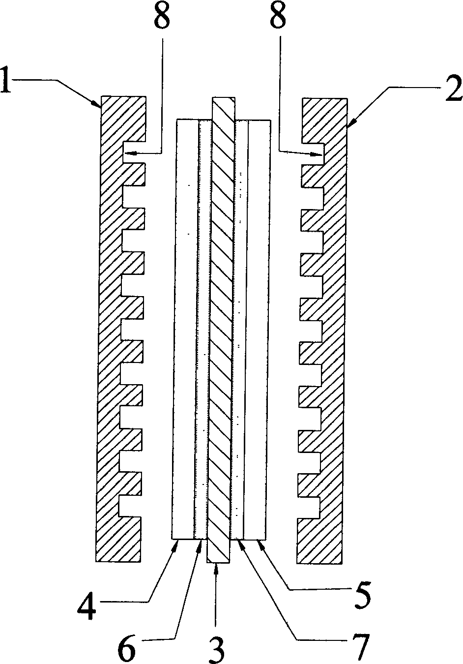
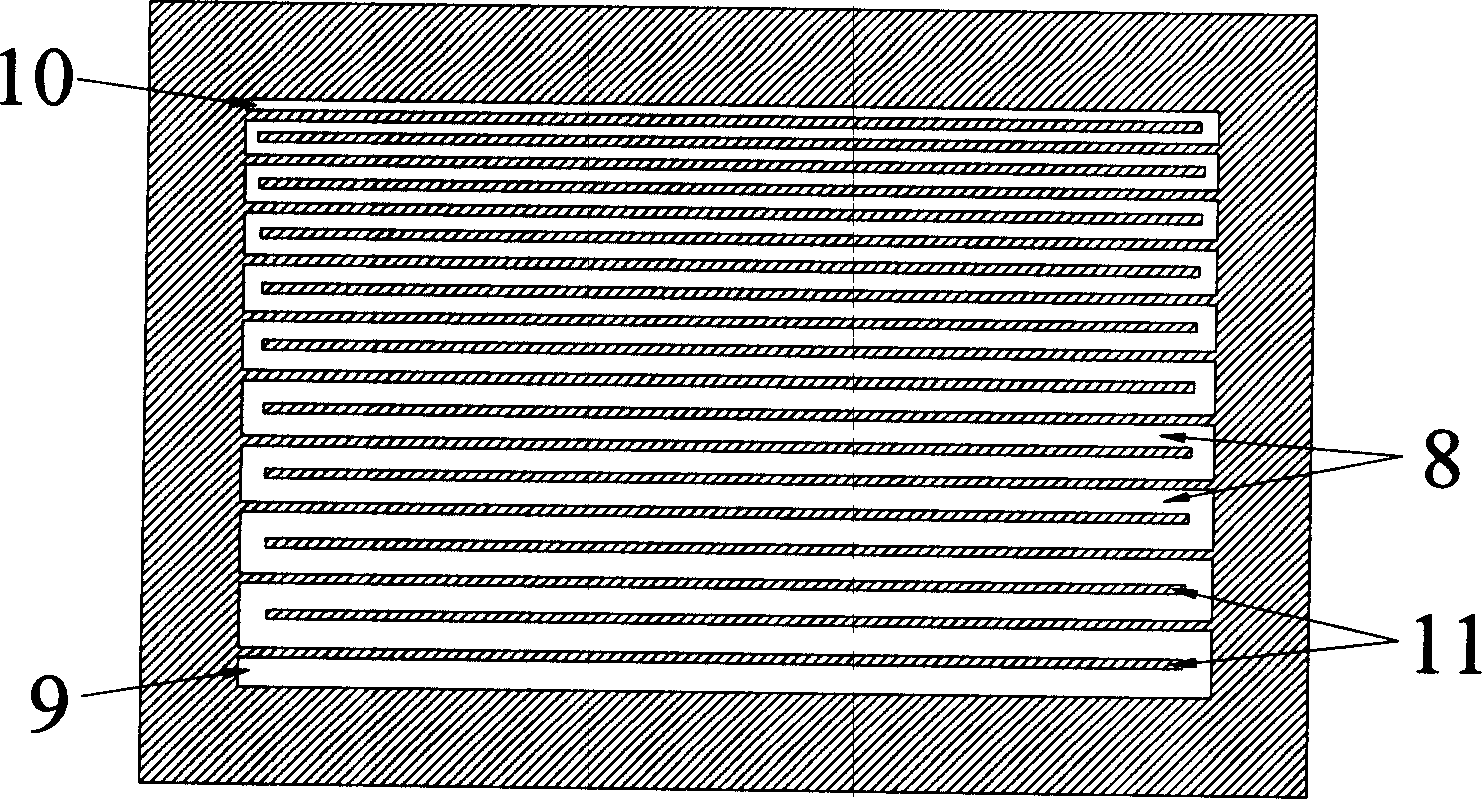
[0040] Made of graphite material such as figure 2 The cathode flow field plate 1 and the anode flow field plate 2 are shown, and the flow field plates have gas inlet 9 and gas outlet 10, and the length, width and thickness of the flow field plates are 120 mm, 80 mm, and 1.5 mm, respectively.

[0041] In this embodiment, the diversion groove 8 on the flow field plate adopts a single diversion groove, and the diversion groove 8 is comb-shaped. The width of the diversion groove 8 gradually decreases from the gas inlet 9 to the gas outlet 10, the width of the first diversion groove on the side of the gas inlet is 3 mm, the second is 2.9 mm, the third is 2.8 mm..., the width Decrease by 0.1 mm in turn, the width of the div...

Embodiment 2

[0043] This embodiment provides a fuel cell flow field plate in which the number and width of the flow guide grooves are constant but the depth of the flow guide grooves is changed. The depth of the diversion groove on the flow field plate changes linearly.

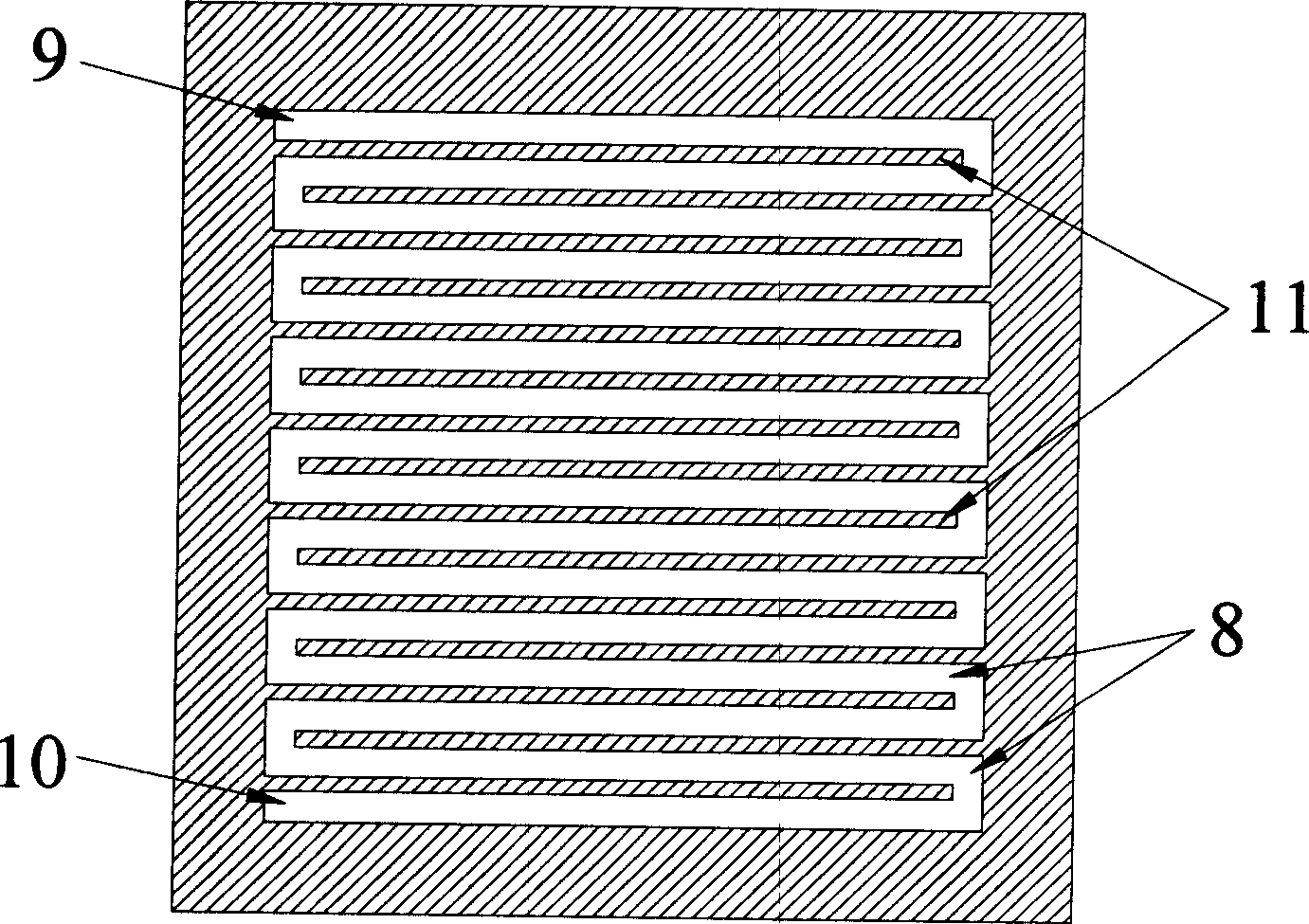
[0044] Made of graphite material such as image 3 The cathode flow field plate 1 and the anode flow field plate 2 are shown, and there are gas inlet 9 and gas outlet 10 on the flow field plate, and the length, width and thickness of the flow field plate are 60 mm, 60 mm and 2.5 mm respectively.

[0045] In this embodiment, the diversion groove 8 on the flow field plate adopts a single diversion groove, the width of the diversion groove 8 is 2 mm, the thickness of the plate ridge 11 is 1 mm, and the depth of the diversion groove 8 is from The gas inlet 9 to the gas outlet 10 gradually decreases, the depth of the diversion groove on the gas inlet side is 1.5 mm, and the depth of the diversion groove on the gas outlet side ...


PUM

PropertyMeasurementUnit
thicknessaaaaaaaaaa

Abstract

This invention relates to a flow-field plate of a fuel battery including a cathode flow field plate and an anode flow field plate, in which, flow slots, gas inlets and outlets are set on them, one side of the slot is connected with the inlet, the other side is connected with the outlet, in which, the flow slot section area closing to the gas inlet on the plate is bigger than that of closing to the outlet, which increases the section area of the flow slot closing to the inlet side to slow down water-loss of proton exchange films to increase the generation performance of fuel batteries and reduces the section area of the slot closing to the outlet to increase the drain ability of the slot.

Description

technical field [0001] The invention belongs to the field of fuel cells, and relates to a flow field plate of a fuel cell, in particular to a flow field plate of a proton exchange membrane fuel cell. Background technique [0002] Proton exchange membrane fuel cell is a highly efficient and environmentally friendly energy conversion device. It has the advantages of high power density, fast start-up at room temperature, and no electrolyte loss. It is very suitable for electric vehicle power, mobile power and small distributed power generation systems. It uses a proton exchange membrane as an electrolyte, and uses pure hydrogen or hydrogen-rich gas (generally refers to a hydrogen-rich mixed gas generated by hydrocarbons through reforming reactions, containing a certain amount of CO 2 and CO) as fuel, air or pure oxygen as oxidant, and the reaction product is water. The chemical reaction of this battery is as follows: [0003] anode: <chemistry num="001"> <chem file...

Claims


Application Information

Patent Timeline
Patent Type & Authority Applications(China)
IPC IPC(8): H01M8/02H01M4/86
CPCH01M8/0263H01M8/0265H01M8/04291Y02E60/50
Inventor 董俊卿
Owner BYD CO LTD
Why Eureka
Try Eureka