Automotive leather cutting station

A technology of cutting table and turntable, which is applied in leather punching/punching/cutting, raw hide/leather/fur manufacturing equipment, small raw hide/large raw hide/leather/fur treatment, etc.

Inactive Publication Date: 2006-11-01
SETON SOUTH AFRICA
View PDF0 Cites 7 Cited by
  • Summary
  • Abstract
  • Description
  • Claims
  • Application Information

AI Technical Summary

Problems solved by technology

And the worker always needs to go back to the tool rack position to take another cut film and place it on the sheet

Method used


Image

  • Automotive leather cutting station
  • Automotive leather cutting station
  • Automotive leather cutting station

Examples


Embodiment Construction

[0019] For purposes of the ensuing description, the terms "upper", "lower", "right", "left", "vertical", "horizontal", "top", "bottom", "lateral", "horizontal" and derivatives thereof , all relevant to the present invention, are oriented in the drawings. It should be understood, however, that the invention is capable of various alternative variations unless otherwise specified elsewhere. It should also be understood that the particular devices depicted in the drawings, hereinafter, are merely exemplary of the invention. Therefore, specific dimensions and other physical characteristics related to the embodiments disclosed herein are not limitations of the present invention.

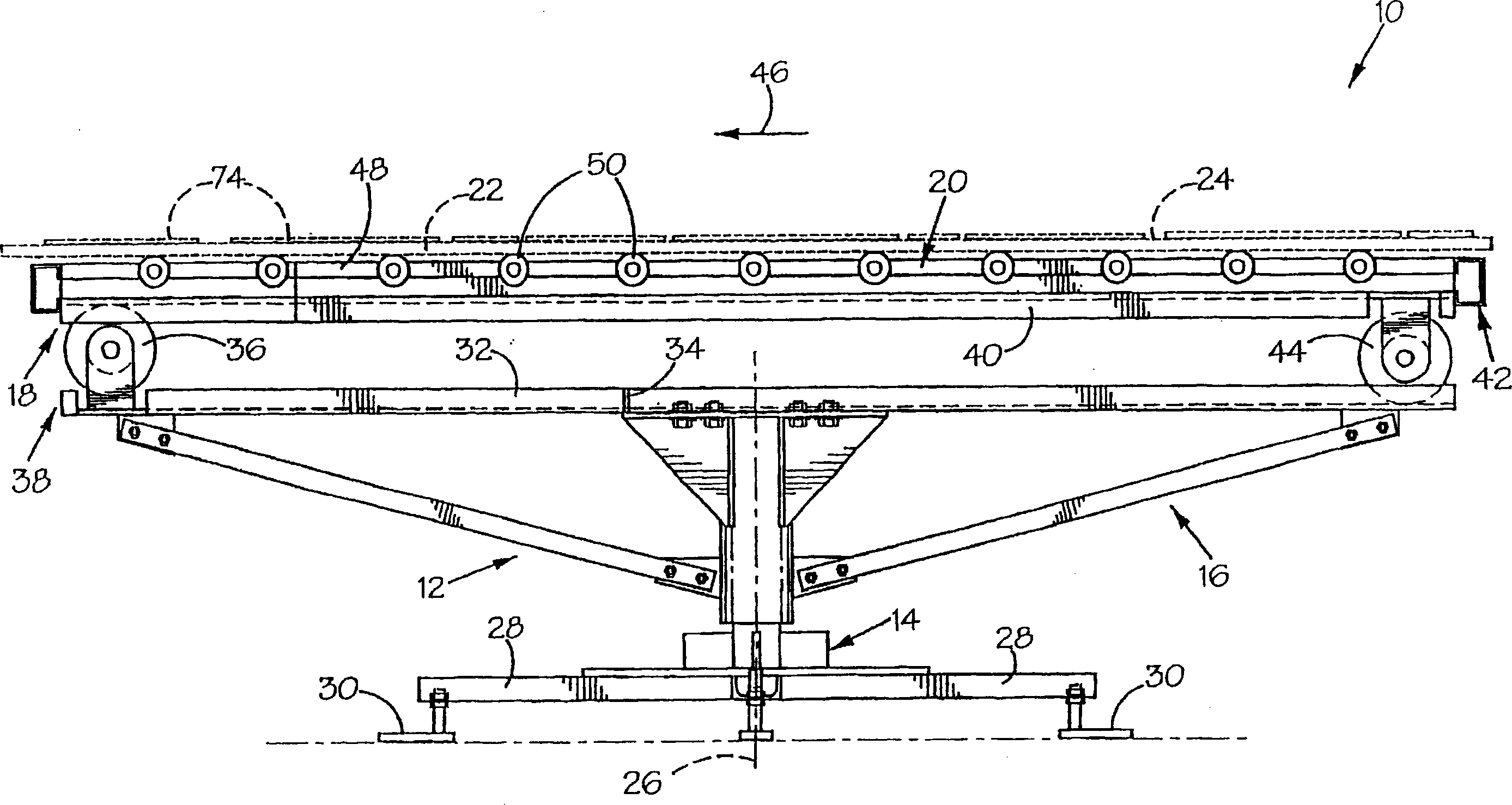
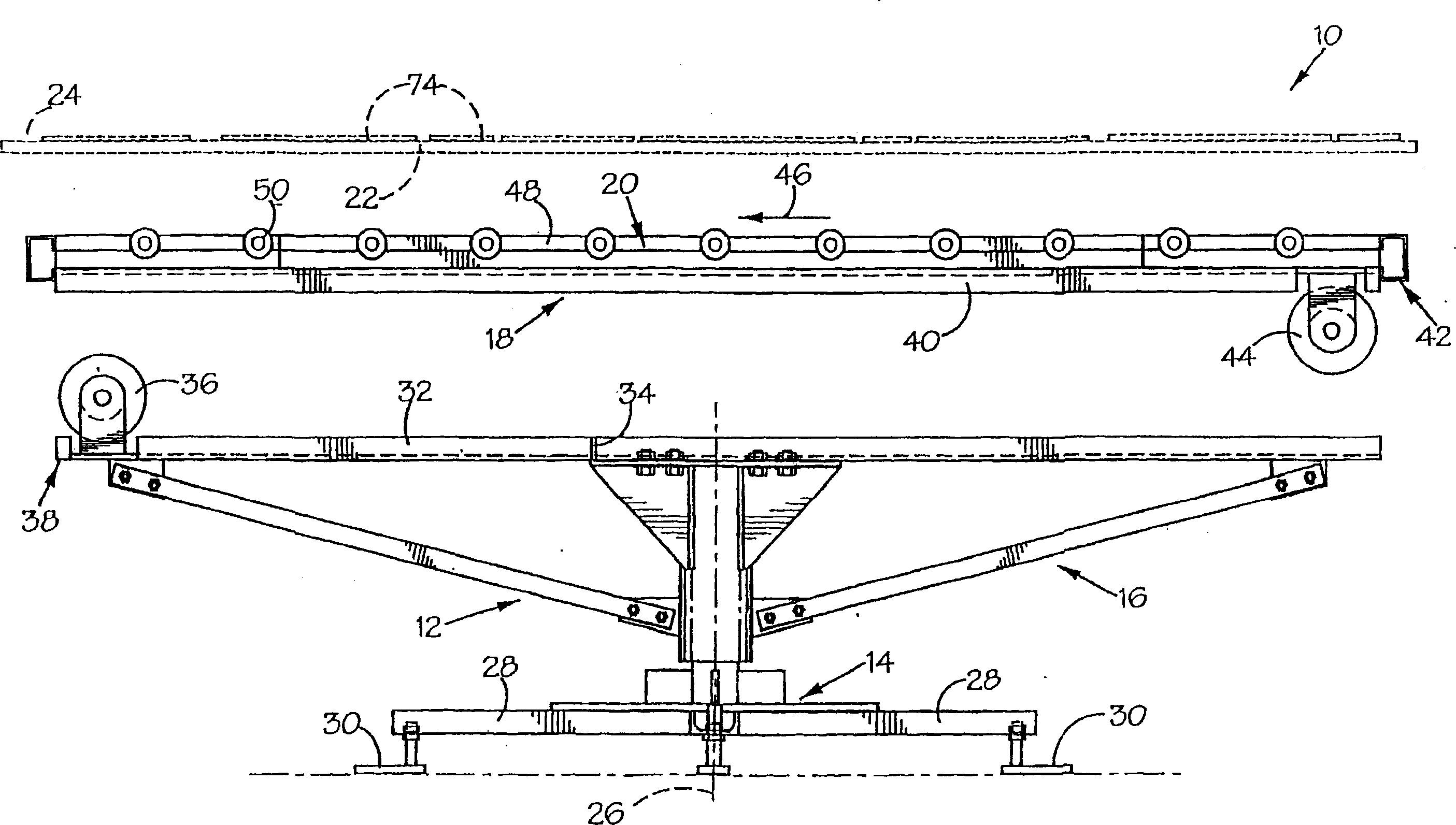
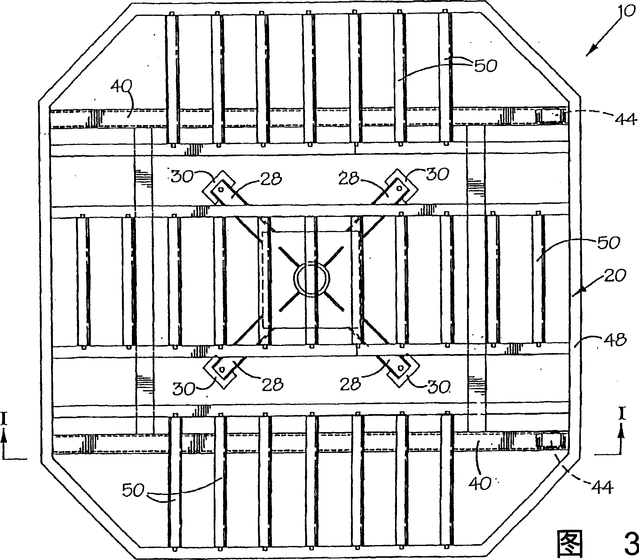
[0020] see figure 1 with 2 , the sheet cutting table 10 includes: a base 12 having a foot member 14 and a turntable member 16 . Cutting table 10 also includes a work surface 18 having supports 20 . The turntable member 16 is rotatably mounted on the base 12 for rotation about a generally vertical axis...


PUM

PropertyMeasurementUnit
diameteraaaaaaaaaa

Abstract

A sheet material cutting table includes a base comprising a foot component and a turntable component and a table top rotatably supported on the base to rotate about a generally vertical axis. The table top includes a support formation and a planar top component defining a planar work surface. At least one of the base and the table top has a track and at least one of the other of the base and the table top has rolling elements configured to roll along the track thereby allowing the table top to be linearly displaceable in a horizontal plane relative to the base.

Description

technical field [0001] The present invention relates generally to sheet cutting, and more particularly to sheet cutting tables and sheet cutting stations. Background technique [0002] Traditional systems for cutting large sheets often require large beds to flatten and position the sheet. The cutting die is then manually placed on the sheet. This requires workers to walk around the bed and place the cutting dies in place. And the worker always needs to return to the position of the tool rack to take another cut film and place it on the sheet. [0003] Cutting of large sheets of material, such as leather or the like, is therefore often a labor-intensive process requiring a large work area. [0004] Therefore, there is a need for sheet material cutting equipment, which can save time and space, thereby improving the work efficiency and economic benefits of the cutting process. Contents of the invention [0005] The object of the present invention is to provide a sheet mat...

Claims


Application Information

Patent Timeline
Patent Type & Authority Applications(China)
IPC IPC(8): B26D7/20B26D1/10B26D7/00B26D7/26C14B5/00
CPCB26D7/015B26D7/0616B26D2007/0056B26F1/3813C14B5/00C14B17/04
Inventor N·斯奈德
Owner SETON SOUTH AFRICA
Why Eureka
Try Eureka