Control valve for a hydraulic brake booster

a technology of hydraulic brake booster and control valve, which is applied in the direction of braking system, rotary clutch, fluid coupling, etc., can solve the problems of increasing and achieve the effect of reducing the noise level of the brake booster operation

Active Publication Date: 2006-01-31
ROBERT BOSCH CORP
View PDF10 Cites 0 Cited by
  • Summary
  • Abstract
  • Description
  • Claims
  • Application Information

AI Technical Summary

Benefits of technology

[0004]A advantage of the present invention resides in a control valve for a brake booster in a brake system having a shuttle member with a stem on a first end that controls the metering of pressurized fluid from a source to an actuation chamber during a brake application and a second end with an annular projection that controls metering of pressurized fluid from the actuation chamber to a reservoir on terminate the brake application such that fluid only flows in a same direction and as a result oscillation of the shuttle is attenuated and the noise level of the operation of the brake booster is reduced.
[0006]An advantage of this invention resides in a shuttle member for a control valve having a stem on a first end and an annular projection whereby pressurized fluid is first metered on being presented to an actuation chamber and second metered on be released from the actuation chamber to a reservoir to such that movement of the shuttle member is substantially linear.
[0007]A further advantage of this invention resides in a shuttle member for a control valve wherein an end of a stem has an annular shape that transitions into a conical shape such that the flow of pressurized fluid from a source through an orifice is essentially a function of the conical shape and increased with the movement of the conical shape into the orifice.

Problems solved by technology

In addition, as a result of the rapid opening and closing of the control valve during a ECU generated brake application, an increase in the level of noise created as pressurized fluid flows to the actuation chamber and on released from the brake chamber may occur.

Method used


Image

  • Control valve for a hydraulic brake booster
  • Control valve for a hydraulic brake booster
  • Control valve for a hydraulic brake booster

Examples


Embodiment Construction

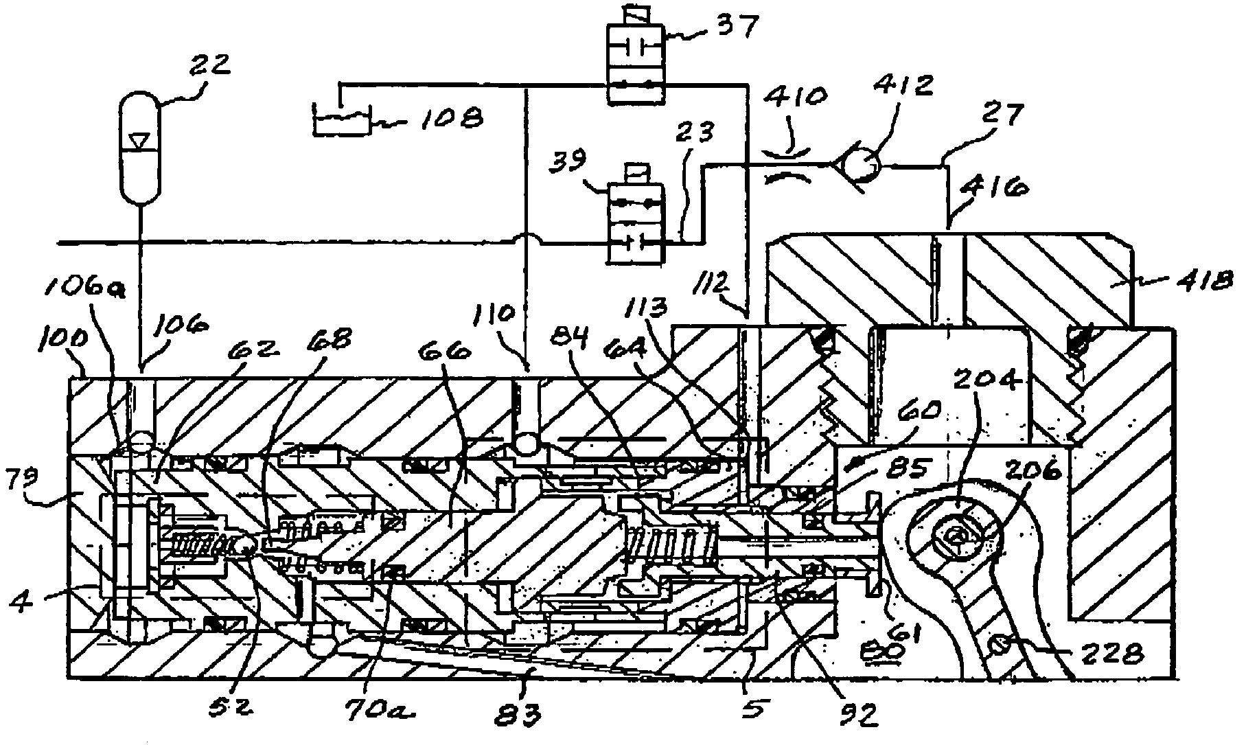
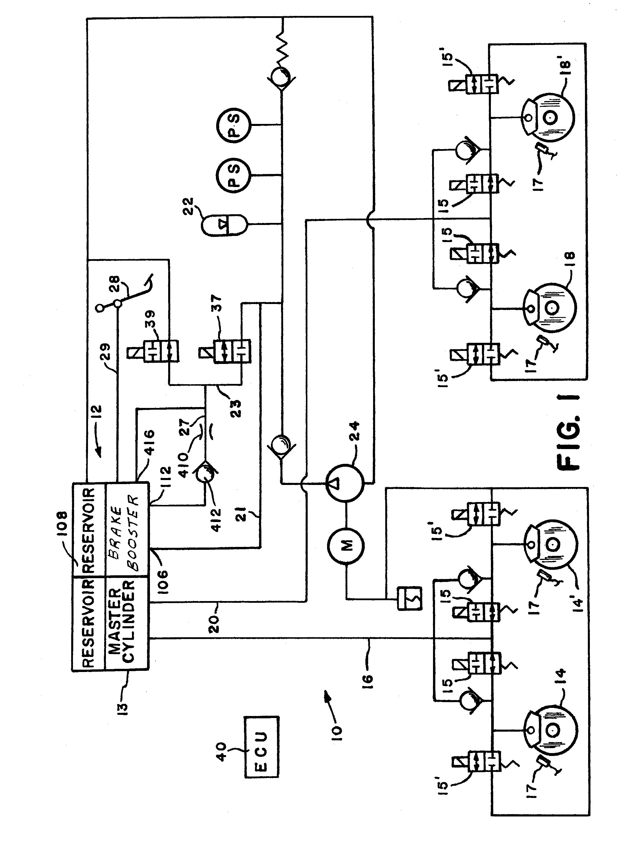
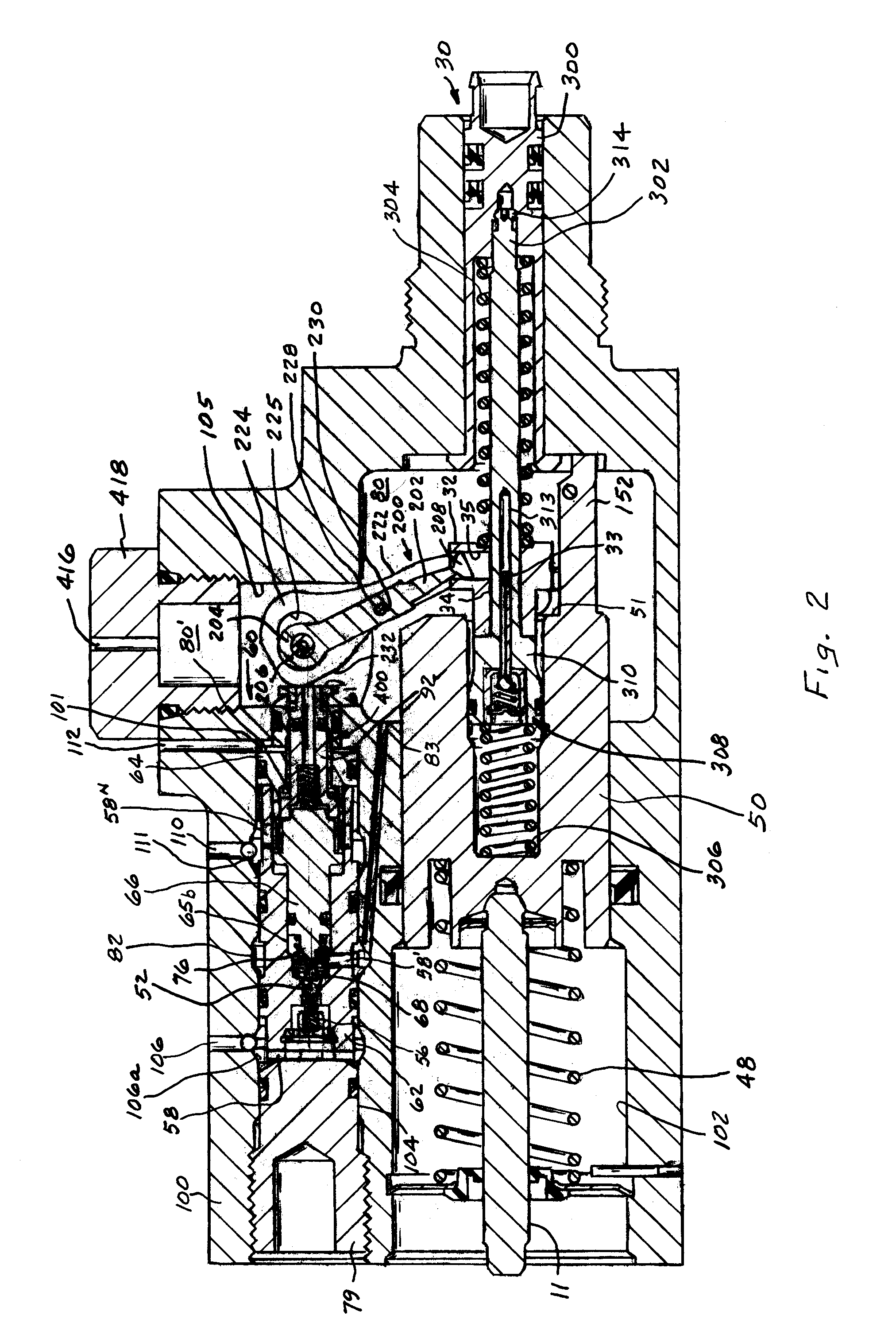
[0019]The brake system 10 as shown in FIG. 1 and details of the components thereof shown in FIGS. 2–11, includes a hydraulic brake booster 12 for supplying a master cylinder 13 wherein an operational force derived from pressurized fluid is supplied to a first set of wheel brakes 14,14″ by a first conduit 16 and to a second set of wheel brakes 18,18″ by a second conduit 20 to effect a brake application. The hydraulic brake booster 12, which is commonly referred to as a closed center booster, receives pressurized supply fluid a source, either directly from a pump 24 or an accumulator 22 that is charged and maintained to a predetermined fluid pressure level by pump 24.

[0020]The brake booster 12 may function in several modes of operation including a manual mode, a boost mode, a boost plus manual mode all of which are under the control of an operator or an electronic mode that is under the control of an ECU 40. In the manual mode, a brake force from an operator is transmitted directly fr...


PUM


Abstract

A control valve of a hydraulic brake booster for use in a brake system. The control valve is characterized by a shuttle member having a stem on a first end and an annular projection on a second end. The stem has an annular surface thereon that is matched with an orifice from an supply chamber such that metered pressurized fluid is uniformly presented to an actuation chamber to effect a brake application while the annular projection is matched with a flange on an actuator piston such that the pressurized fluid present in the actuation chamber is uniformly metered to a reservoir.

Description

BACKGROUND OF INVENTION[0001]This invention relates to a control valve for a hydraulic brake booster having a shuttle member with a first end to control metering of pressurized fluid to an actuation chamber during a brake application and a second end to control metering of pressurized fluid from the actuation chamber to a reservoir on termination the brake application.[0002]In hydraulic brake boosters of a type disclosed in U.S. Pat. Nos. 4,281,585; 4,539,892; 4,625,515; 6,561,596 and U.S. Pat. No. 6,732,578, a control valve is located in a first bore and a power piston is located in a second bore of a housing. A lever arrangement is connected to the power piston and the control valve. An input force applied to a brake pedal by an operator acts on the lever arrangement to develop a manual mode and a power assist mode of operation. The lever arrangement pivots on the power piston and communicates an actuation force that moves the control valve to regulate the flow of pressurize fluid...

Claims


Application Information

Patent Timeline
Patent Type & Authority Patents(United States)
IPC IPC(8): B60T13/20B60T8/48B60T13/00B60T13/14
CPCB60T8/4845B60T13/147B60T13/142
Inventor MCCLAIN, RICHARD BECKERPENNINGER, WILLIAM JOHNDOTY, GARY L.ALBERT, TIMOTHY J.
Owner ROBERT BOSCH CORP
Why Eureka
Try Eureka