MEMS Scan Controller Generating Clock Frequency and Control Method Thereof

a microelectronicmechanical system and scan controller technology, applied in the direction of optical elements, instruments, optical radiation measurement, etc., can solve the problems of raising associated control difficulties, inability to meet high speed and high precision requirements by using polygon mirrors, etc., and achieve the effect of stabilizing the oscillation of the mems mirror

Inactive Publication Date: 2011-06-02
E PIN OPTICAL IND
View PDF20 Cites 31 Cited by
  • Summary
  • Abstract
  • Description
  • Claims
  • Application Information

AI Technical Summary

Benefits of technology

[0005]Therefore it is a primary object of the present invention to provide a MEMS scan controller applied to bi-direction laser scanning units (LSU). The MEMS scan controller is for detecting resonant frequency and amplitude of the MEMS mirror so as to generate signals to laser controllers and control bridge circuit of the MEMS mirror for adjusting resonant frequency and amplitude of the MEMS mirror and stabilizing the oscillation of the MEMS mirror. Thus the laser beam can perform scanning precisely and correctly within effective scanning window.

Problems solved by technology

However, due to hydraulic driving, working rotational speed limits, high manufacturing cost, high noises and delayed initiation, such LSU is unable to meet requirements of high speed and high precision by using polygon mirror.
In order to improve scanning efficiency, a bi-directional LSU is developed yet associated control difficulties are raised.

Method used


Image

  • MEMS Scan Controller Generating Clock Frequency and Control Method Thereof
  • MEMS Scan Controller Generating Clock Frequency and Control Method Thereof
  • MEMS Scan Controller Generating Clock Frequency and Control Method Thereof

Examples


embodiment one

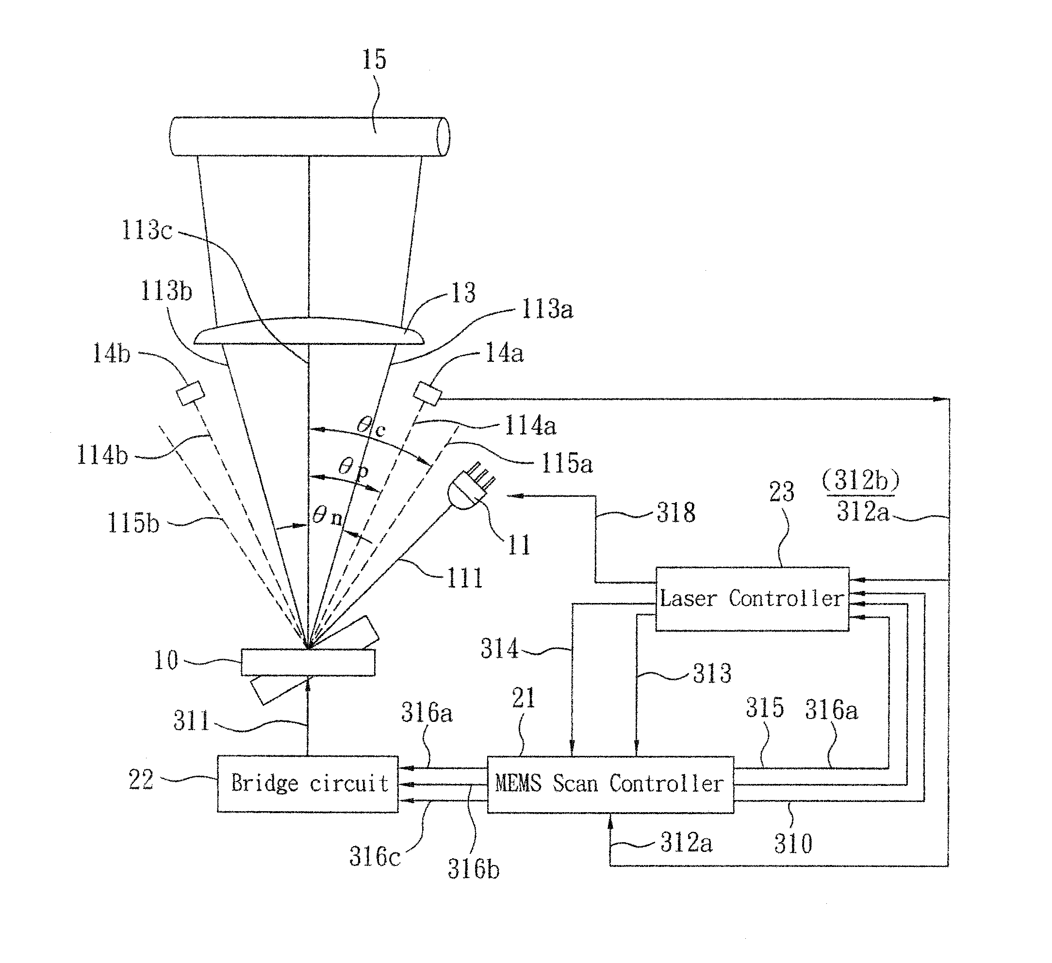
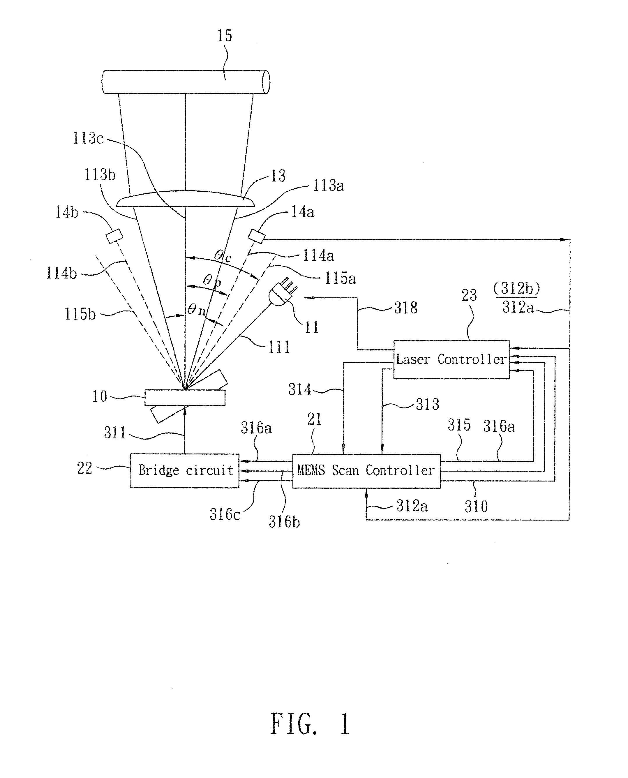
[0048]Refer to FIG. 1, a MEMS LSU with one PD detectors is disclosed. A pre-scan laser 11 is controlled by a laser controller 23. When the laser controller 23 sends out scanning data 318, the pre-scan laser 11 emits laser light 111 toward a MEMS mirror 10 that oscillates in resonant frequency f. In this embodiment, the MEMS mirror 10 whose f=2500±5% HZ and maximum scanning angle±23° is used. The laser light 111 with scanning angle of ±23*2° (θc=±23*2°) ranges from right-side scanning beam 115a to left-side scanning beam 115b. The scanning beam ranging from 113a to 113b is within angle of 2θn. In this embodiment, the θn=±19*2°, and is called effective scanning window. A PD detector 14a is disposed at θp while θp=±21*2° for detecting scanning beam 114a and converting light into electric trigger signal. The scanning beams 113a-113b pass a post-scan lens 13 and form an image on an object 15 such as a photo conductor. In order to keep stability of the angle 2θc, the MEMS mirror 10 is con...

embodiment two

[0074]This embodiment is applied to a MEMS LSU with a PD detector. The control method of the MEMS scan controller 21 according to this embodiment is the same with that of the above embodiment. In order to send the scan data 318 more precisely, when the MEMS scan controller 21 sends the clock signal 310 with frequency of fCLK(t), the data trigger signal 317a is also sent simultaneously thereby for driving the laser controller 23 to start sending the scan data 318. Refer to FIG. 12, once the control logic 211 of the MEMS scan controller 21 receives the ENB signal 313, it sends the clock signal 310 as well as the data trigger signal 317a. The method of this embodiment to send the scan data includes following steps:[0075]S1: if the ENB signal 313 from the laser controller 23 is at low voltage, the MEMS scan controller 21 will not send the CLK signal 310 as well as the data trigger signal 317a. Once the laser controller 23 sends the ENB signal 313 or the adjust signal 314, the MEMS scan ...

embodiment three

The Embodiment Three

[0079]This embodiment is applied to a MEMS LSU with a PD detector. The control method of the MEMS scan controller 21 according to this embodiment is the same with that of the first embodiment. The MEMS scan controller 21 of this embodiment further comprises a RF delay circuit 216 that delays the input resonant frequency signal 321 and not sending the data trigger signal 317b until generation of pulse of the first modulation signal 316a. The data trigger signal 317b drivers the laser controller 23 starting to send the scan data 318. As shown in FIG. 13, once the control logic 211 of the MEMS scan controller 21 receives the stable signal 315, it sends the clock signal 310 as well as the data trigger signal 317a. The method of this embodiment to send the scan data includes following steps:[0080]S1: if the ENB signal 313 from the laser controller 23 is at low voltage, the MEMS scan controller 21 will not send the CLK signal 310 as well as the data trigger signal 317b...


PUM


Abstract

A Micro Electronic Mechanical System (MEMS) scan controller generating clock frequency and a control method thereof are disclosed. The MEMS scan controller is for a MEMS mirror in a bi-direction laser scanning units (LSU). By detecting resonant frequency of the MEMS mirror, the scan controller sends frequency modulation signal and amplitude modulation signal of the MEMS mirror to a bridge circuit of the MEMS mirror for adjusting and stabilizing the MEMS mirror. A clock signal corresponding to the resonant frequency of the MEMS mirror at the moment is also sent so that scan data is sent within the effective scanning window in forward direction/reverse direction. Thus high-precision scanning is achieved.

Description

BACKGROUND OF THE INVENTION[0001]The present invention relates to a Micro-electronic-mechanical System (MEMS) scan controller generating clock frequency and a control method thereof, especially to a controller for micro-electric-mechanical mirrors (MEMS mirror) applied to bi-direction laser scanning units (LSU) and a control method that generate clock frequency signals so as to make a laser light source transmit laser beams within an effective scanning window according to the clock frequency signals.[0002]Most of LSU available now uses a polygonal mirror rotating at high speed to control reflection direction of laser beam. However, due to hydraulic driving, working rotational speed limits, high manufacturing cost, high noises and delayed initiation, such LSU is unable to meet requirements of high speed and high precision by using polygon mirror. In recent years, MEMS mirrors with torsion oscillators are getting known and are going to be applied to LSU of imaging systems, scanners or...

Claims


Application Information

Patent Timeline
Patent Type & Authority Applications(United States)
IPC IPC(8): G01J1/16G02B26/10
CPCG02B26/105
Inventor YEN, WEI-SHIN
Owner E PIN OPTICAL IND
Why Eureka
Try Eureka