Laser composite wave appts.
A laser and laser technology, which is applied in the field of laser multiplexing devices, can solve the problems of difficult manufacturing and difficult manufacturing of redirection systems.
- Summary
- Abstract
- Description
- Claims
- Application Information
AI Technical Summary
Problems solved by technology
Method used
Image
Examples
Embodiment 1-1
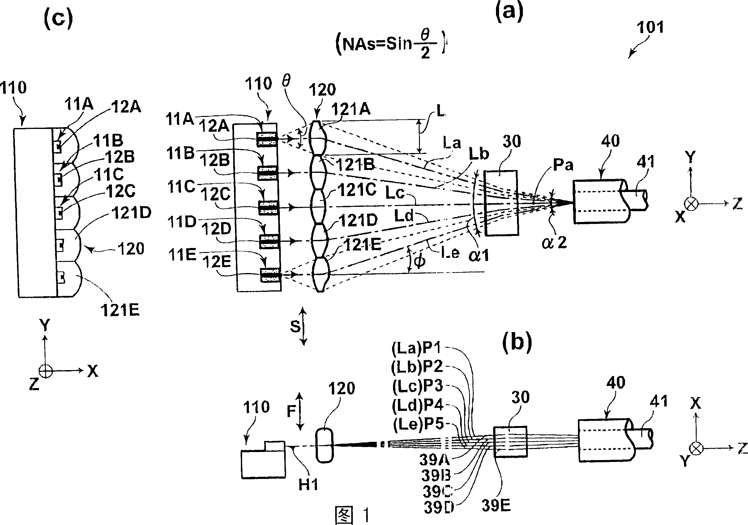
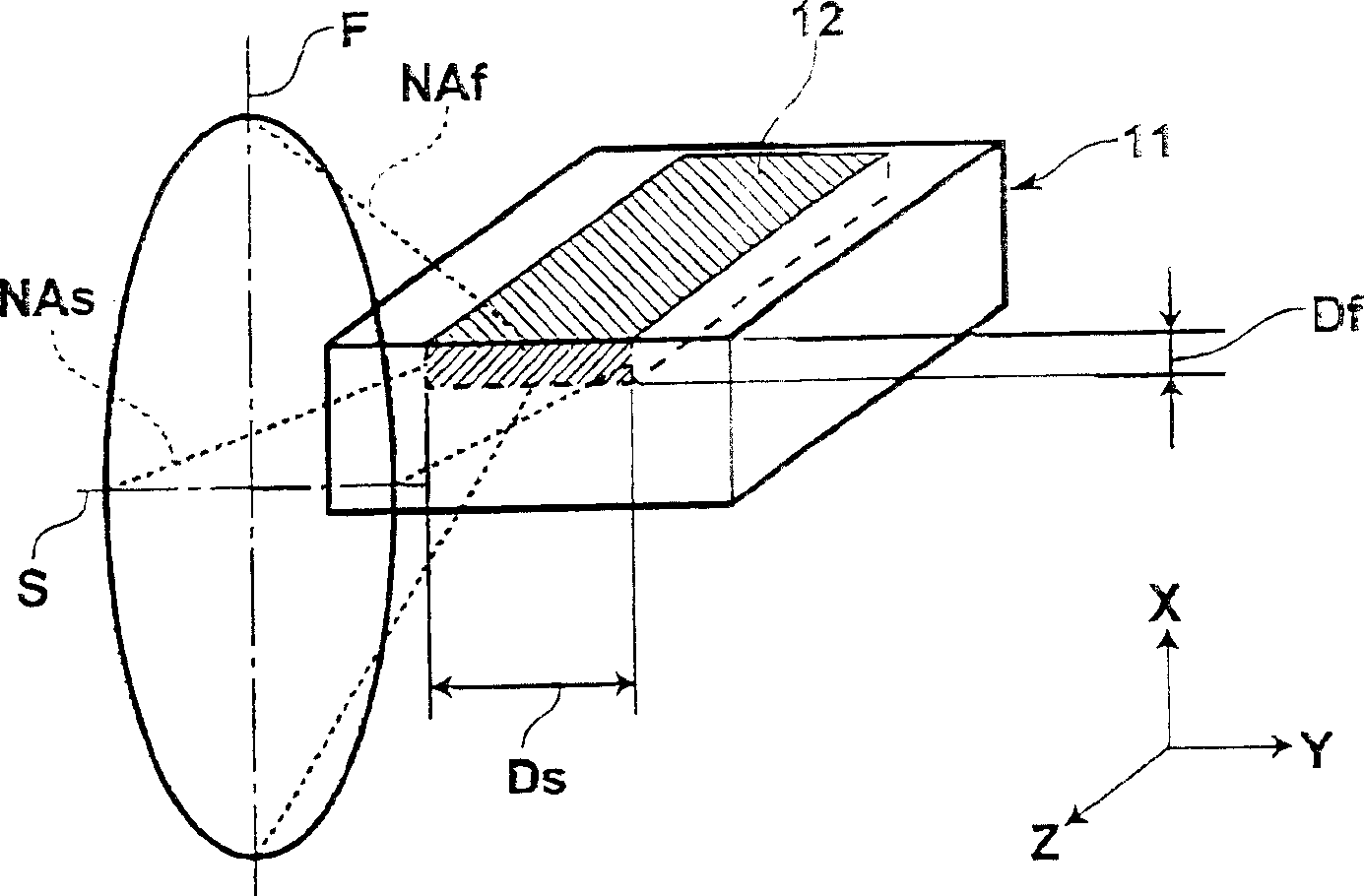
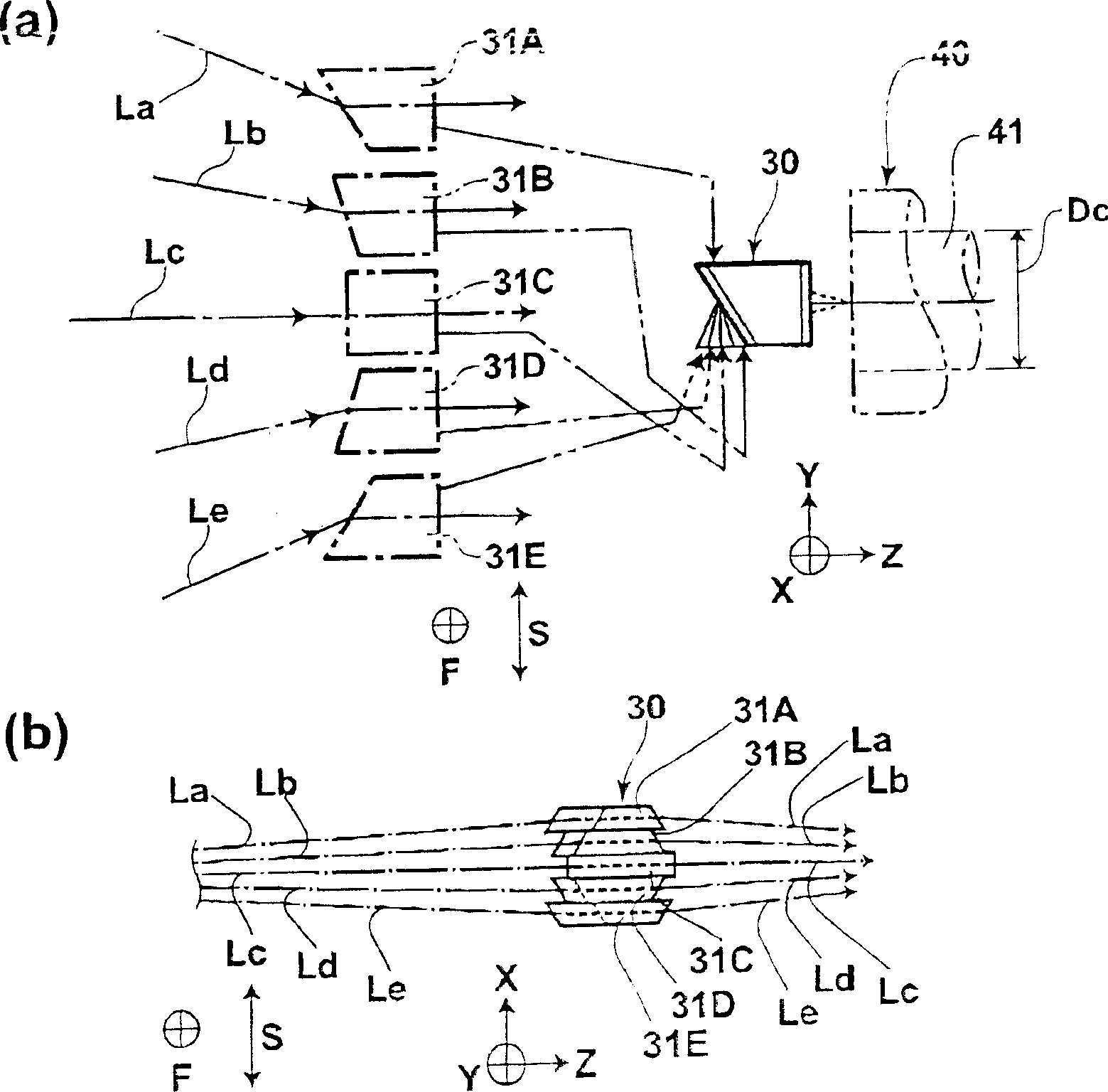
[0123] Fig. 1 is a schematic configuration diagram showing a laser combining device of the first example (hereinafter referred to as Example 1-1) in the first embodiment of the present invention, and Fig. 1(a) is a view of the above-mentioned laser combining device from above. The top view of the wave device, Fig. 1 (b) is the front view of the above-mentioned laser multiplexing device observed from the semiconductor laser arrangement direction, and Fig. 1 (c) is the left side view of the above-mentioned laser multiplexing device observed from the optical axis direction of the light beam. in addition, figure 2 It is a perspective view showing a state where a laser beam is emitted from an active layer of a semiconductor laser, image 3 It is a state diagram showing the structure of the focusing angle conversion optical system and the beams multiplexed in the optical fiber through the focusing angle conversion optical system, image 3 (a) is a plan view showing the structure o...
Embodiment 1-2
[0138] Hereinafter, a laser multiplexing device of a second example (hereinafter referred to as example 1-2) in the first embodiment of the present invention will be described. Figure 5 is a schematic configuration diagram showing the above-mentioned laser multiplexing device, Figure 5 (a) is a top view of the laser combining device observed from above, Figure 5 (b) is a top view of the laser multiplexing device observed from the direction in which the semiconductor lasers are arranged, Figure 5 (c) is a left side view of the laser multiplexing device observed from the optical axis direction of the beam, Image 6 is a functional diagram showing the deflection of light beams by individual lenses constituting the deflection lens, Image 6 (a) is a schematic diagram of the above-mentioned individual lens viewed with the Y direction as the upper side of the paper, Image 6 (b) is a schematic diagram of the above-mentioned individual lenses viewed with the X direction as the...
Embodiment 2-1
[0157] Figure 9 It is a schematic configuration diagram showing the laser multiplexing device 201 of the first example (hereinafter referred to as Example 2-1) in the second embodiment of the present invention, Figure 9 (a) is the plan view that observes above-mentioned laser multiplexing device from above, Figure 9 (b) is a front view of observing the above-mentioned laser multiplexing device from the laser arrangement direction, Figure 9 (c) is to observe above-mentioned laser multiplexing device figure from the optical axis direction of light beam, Figure 10 It is a diagram showing a state in which the focusing angle conversion optical system converges the optical axes of the respective light beams parallel to each other in the slow-axis direction view. Such as Figure 9 As shown, the laser multiplexing device 201 of the embodiment 2-1 includes the laser block 10, all the focusing optical systems 20, and the focusing angle conversion optical system 30C.
[0158] In...
PUM
| Property | Measurement | Unit |
|---|---|---|
| Wavelength | aaaaa | aaaaa |
| Core diameter | aaaaa | aaaaa |
| Core diameter | aaaaa | aaaaa |
Abstract
Description
Claims
Application Information
 - R&D
- Intellectual Property
- Life Sciences
- Materials
- Tech Scout
- Unparalleled Data Quality
- Higher Quality Content
- 60% Fewer Hallucinations
Browse by: Latest US Patents, China's latest patents, Technical Efficacy Thesaurus, Application Domain, Technology Topic, Popular Technical Reports.
© 2025 PatSnap. All rights reserved.Legal|Privacy policy|Modern Slavery Act Transparency Statement|Sitemap|About US| Contact US: help@patsnap.com


