Oscillator

a technology of oscillator and oscillator, which is applied in the direction of oscillator, pulse generator, pulse technique, etc., can solve the problems of disturbance of the pattern of radiated electromagnetic waves, and achieve the effect of improving the stability of oscillation output in the terahertz frequency rang

Inactive Publication Date: 2012-01-05
CANON KK
View PDF1 Cites 15 Cited by
  • Summary
  • Abstract
  • Description
  • Claims
  • Application Information

AI Technical Summary

Benefits of technology

[0017]This structure is substantially equivalent to the structure in which a stabilizing circuit is directly arranged on the resonator section. Accordingly, the parasitic oscillation can be suppressed in the waveleng

Problems solved by technology

In addition, there is also a risk that the pattern of

Method used


Image

  • Oscillator
  • Oscillator
  • Oscillator

Examples


examples

[0056]Examples of the present invention will now be described in detail.

first example

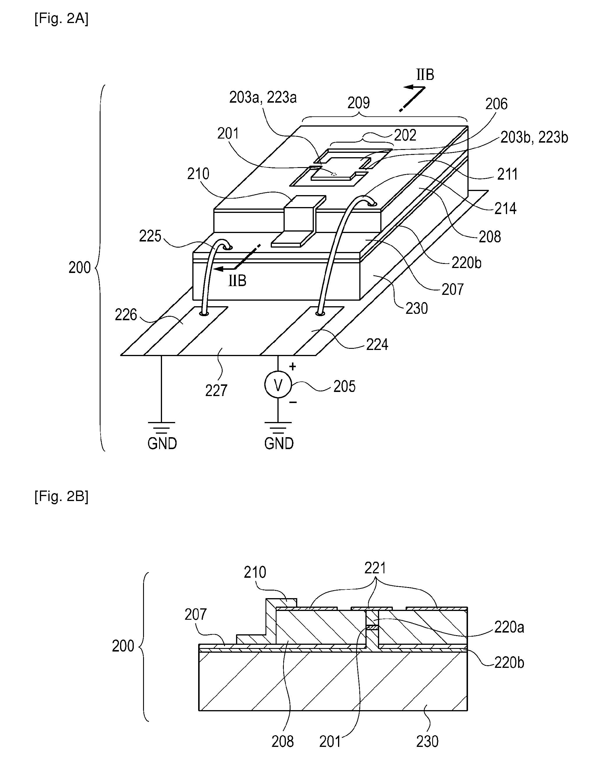
[0057]An oscillator according to a first example will be described with reference to FIGS. 2A to 4B. FIG. 2A is an external view illustrating the first example. FIG. 2B is a sectional view illustrating the first example. FIGS. 3A and 3B are graphs illustrating an example the result of admittance analysis of the oscillator according to the first example. FIGS. 4A and 4B are external views illustrating modifications of the first example.

[0058]The structure of an oscillator 200 according to the first example will now be described. The oscillator 200 according to the first example is a terahertz oscillator formed on a substrate 230 and is mainly composed of an RTD 201, a patch antenna resonator 202, lines 203a and 203b, an MIM structure 209, and a bismuth resistor 210.

[0059]The RTD 201 has a triple-barrier quantum well structure.

[0060]First Barrier Layer: AlAs, 1.3 nm

[0061]First Quantum Well Layer: InGaAs, 7.6 nm

[0062]Second Barrier Layer: InAlAs, 2.6 nm

[0063]Second Quantum Well Layer: ...

second example

[0080]A second example, in which the resonator has a waveguide structure, will be described with reference to FIGS. 5A and 5B. An oscillator according to the second example includes a resonator having a plasmon waveguide structure. The plasmon waveguide structure is structured such that RTDs 401 are disposed in a resonator including two electrodes 406 and 407 and a dielectric layer 408 interposed therebetween. According to the second example, the output level of the oscillator can be increased. In FIGS. 5A and 5B, reference numeral 414 denotes a feeder line.

[0081]The RTDs 401 may be formed continuously in a direction perpendicular to the figures (not shown). In addition, as shown in FIGS. 5A and 5B, the RTDs 401 may be periodically arranged in the resonator. In this case, the oscillator according to the second example can be structured such that a plurality of lines (for example, lines 403a and 403b) are connected to respective ports 1 at which nodes of the standing wave that resona...


PUM


Abstract

An oscillator includes a resonator section structured such that a dielectric is interposed between first and second conductors and such that the first and second conductors are electrically connected to a resonant tunneling diode, a capacitor section structured such that the dielectric is interposed between the first and second conductors, a line section configured to electrically connect the resonator section and the capacitor section in parallel to each other, and a resistor section configured to electrically connect the first and second conductors to each other. A first position of the resonator section and a second position of the capacitor section are connected to each other by the line section so that the first position and the second position are substantially electrically equivalent to each other in a wavelength range larger than a wavelength of an electromagnetic wave that resonates in the resonator section.

Description

TECHNICAL FIELD[0001]The present invention relates to an oscillator including a resonant tunneling diode (RTD) that generates an electromagnetic wave.BACKGROUND ART[0002]A resonant tunneling diode (RTD) is an example of a terahertz oscillator of a current injection type that generates an electromagnetic wave in a frequency range of 30 GHz to 30 THz (referred to as terahertz wave in this description). The RTD is capable of generating the terahertz wave at a room temperature using an electromagnetic wave gain based on electron transition between subbands in a semiconductor quantum well structure.[0003]Patent Literature 1 (Japanese Patent Laid-Open No. 2007-124250) discloses a terahertz oscillator formed by accumulating an active layer composed of a double-barrier RTD and a planar slot antenna resonator on a semiconductor substrate. The oscillator generates an electromagnetic wave by stimulated emission in a range of negative differential resistance in a current-voltage (I−V) character...

Claims


Application Information

Patent Timeline
IPC IPC(8): H03B7/08H03B7/02
CPCH03B7/08H03B7/14
Inventor KOYAMA, YASUSHISEKIGUCHI, RYOTA
Owner CANON KK
Why Eureka
Try Eureka