Low-EMI asymmetrical centre tap rectification circuit

A technology of center tap and rectifier circuit, which is applied in the direction of electrical components, adjusting electric variables, high-efficiency power electronic conversion, etc., can solve the problems of long-time switching tubes on the primary side, electromagnetic interference, etc., and achieve improved conversion efficiency, reduced volume, reduced Effect of small dead time

Active Publication Date: 2017-10-13
ZHEJIANG UNIV
View PDF3 Cites 0 Cited by
  • Summary
  • Abstract
  • Description
  • Claims
  • Application Information

AI Technical Summary

Problems solved by technology

It brings more serious electromagnetic interference problems, and it takes longer to realize the ZVS of the primary switch tube

Method used


Image

  • Low-EMI asymmetrical centre tap rectification circuit
  • Low-EMI asymmetrical centre tap rectification circuit
  • Low-EMI asymmetrical centre tap rectification circuit

Examples


Embodiment Construction

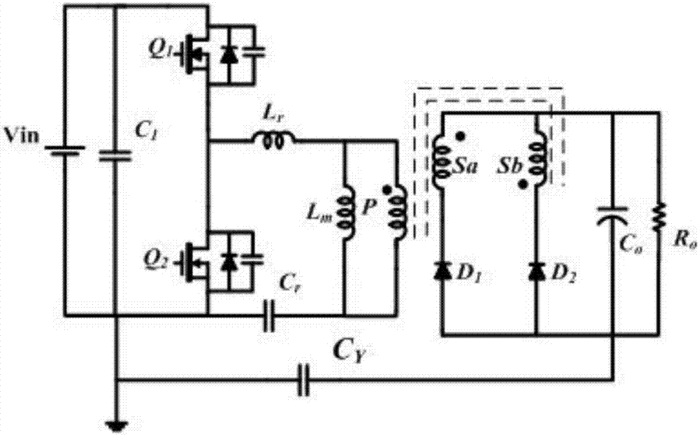
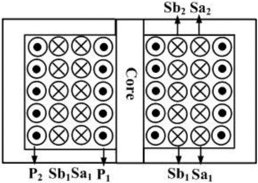
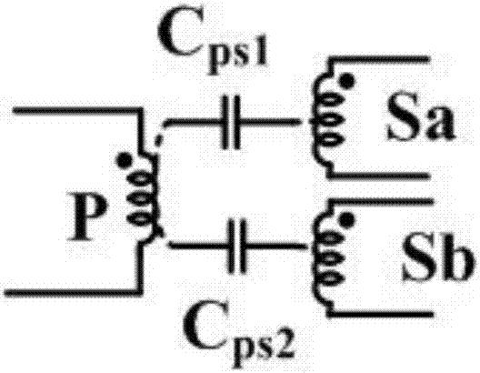
[0032] The low-EMI asymmetric center-tapped rectifier circuit in the present invention has a half-bridge LLC topology as the primary side, and a center-tap rectifier circuit as the rear stage, including a set of bridge arms, a resonant inductor Lr, a resonant capacitor Cr, two rectifier diodes D1, D2, and a power transformer T 1 ; Power transformer T 1 Including the primary winding P, the first secondary winding Sa and the second secondary winding Sb, the power transformer T 1 The primary and secondary windings adopt a staggered winding structure, and the end of the transformer winding with the same name is defined as the positive end and the other is the negative end; it is characterized in that:

[0033] Among the two rectifier diodes D1 and D2, the first rectifier diode D 1 The cathode of the second secondary winding Sb is connected to the output filter capacitor C 0 The positive end of the second rectifier diode D 2 The anode of the first secondary winding Sa is connec...


PUM


Abstract

The invention relates to the field of DC/DC conversion, and aims at providing a low-EMI asymmetrical centre tap rectification circuit. The primary side of the low-EMI asymmetrical centre tap rectification circuit is a half-bridge LLC topology, the back stage is a centre tap rectification circuit; the windings at the primary and secondary sides of a power transformer adopt a staggered wound winding structure; the same-name end of the transformer winding is defined as a positive end and the other end is defined as a negative end; the negative pole of a first rectification diode and a negative end of a second secondary-side winding are connected with the positive end of an output filtering capacitor; the positive pole of a second rectification diode and the negative end of a first secondary-side winding is connected with the negative end of the output filtering capacitor; the positive pole of the first rectification diode is connected with the positive end of the first secondary-side winding; and the negative pole of the second rectification diode is connected with the positive end of the second secondary-side winding. The low-EMI asymmetrical centre tap rectification circuit reduces common-mode current and interference caused by the common-mode current, removes or relieves a current extraction effect from the common-mode current between the primary and secondary sides of the transformer to the current of an excitation inductor, reduces dead time of a bridge wall switch tube and improves the conversion efficiency of a converter.

Description

technical field [0001] The invention belongs to the field of DC / DC conversion and relates to a rectification circuit structure capable of reducing the common mode current of a converter. More specifically, the present invention relates to an asymmetric structure center-tapped rectifier circuit for realizing low common-mode interference current for a power transformer with two secondary windings. Background technique [0002] Electromagnetic Interference (EMI for short) refers to the interference phenomenon caused by the interaction between electromagnetic waves and electronic components. There are two types of conducted interference and radiated interference. [0003] Capacitive output center-tapped rectifier circuits (such as figure 1 ) is widely used in the rectification structure of the DC-DC resonant converter because of its simple structure, no output inductance, easy realization of soft switching of the rectifier tube and many other advantages. However, the high-freq...

Claims


Application Information

Patent Timeline
Patent Type & Authority Applications(China)
IPC IPC(8): H02M1/44H02M3/335
CPCH02M1/44H02M3/33569H02M3/33592H02M1/123Y02B70/10
Inventor 吴新科蓝桂星张思亮
Owner ZHEJIANG UNIV
Why Eureka
Try Eureka