oscillator

a technology of oscillator and oscillator, which is applied in the field of oscillators, can solve the problems of significant decrease in the desired frequency of an oscillation output, and achieve the effect of not easily applied, and the oscillation output generated in the plasmon waveguide serving as a resonator significantly decreases

Active Publication Date: 2016-01-21
CANON KK
View PDF9 Cites 0 Cited by
  • Summary
  • Abstract
  • Description
  • Claims
  • Application Information

AI Technical Summary

Benefits of technology

[0010]In NPL 1, the method for suppressing parasitic oscillation is to be applied to a configuration of a slot-type resonator. Thus, it is not easily applied when a DSM waveguide is used as a resonator. Furthermore, when a structure employing a plasmon waveguide structure as a resonator is used in a RTD oscillator as discussed in NPL 2, parasitic oscillation may occur due to a power supply bias circuit, or unintended resonance may occur due to inner capacitance within the plasmon waveguide structure, or self inductance caused by wiring. As a result, oscillation output generated in the plasmon waveguide serving as a resonator significantly decreases.

Problems solved by technology

Such parasitic oscillation causes a significant decrease in an oscillation output at the desired frequency.

Method used


Image

  • oscillator
  • oscillator
  • oscillator

Examples


Embodiment Construction

[0026]Various exemplary embodiments, features, and aspects of the invention will be described in detail below with reference to the drawings.

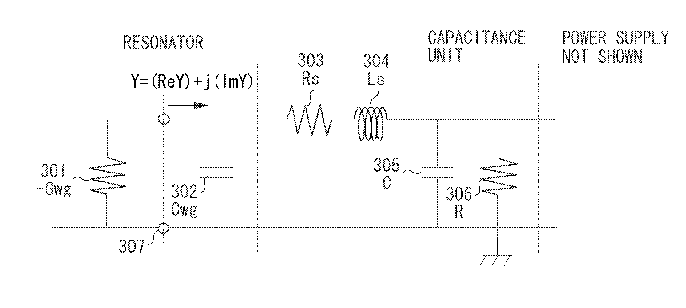
[0027]The oscillator according to an exemplary embodiment of the present invention has a conductance equal to or higher than an absolute value Gwg of negative conductance of a negative resistor at the resonant frequency fLC. The conductance includes an inductance Ls and a resistance component Rs arising from wiring and a capacitance C of a capacitance unit. Namely, the resistance of the wiring and the capacitance unit is set by placing the resonator and the capacitance unit close to each other to make the conductance equal to or higher than an absolute value of the conductance of the negative resistor.

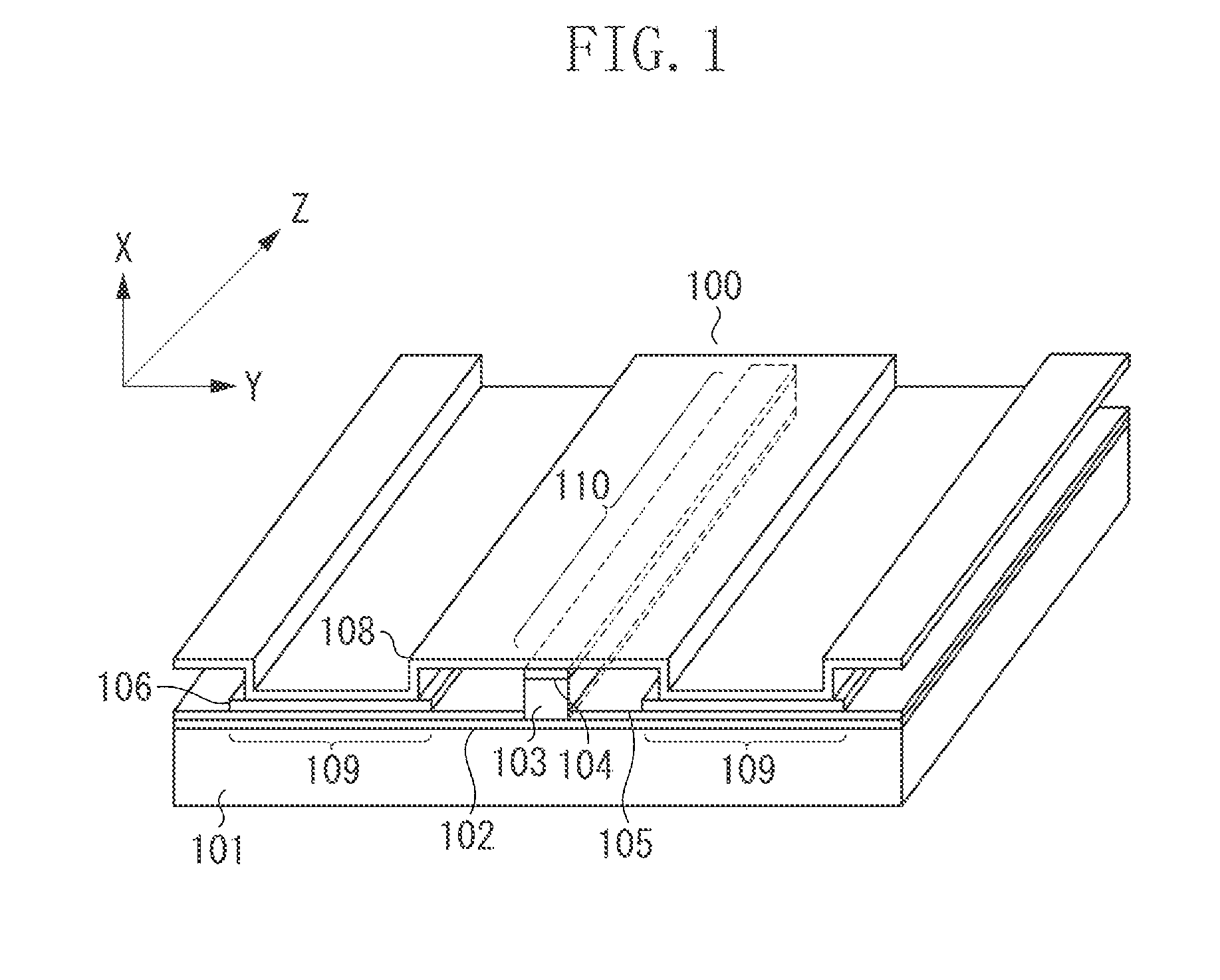
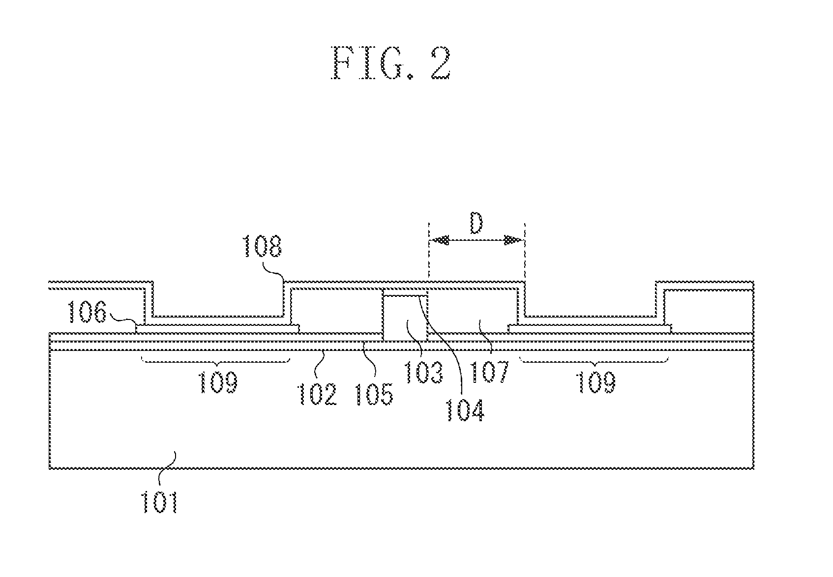
[0028]Exemplary embodiments and examples of the present invention will be described. One exemplary embodiment of the oscillator will be described with reference to FIGS. 1 to 3. In these figures, the oscillator of the present exemplary embodiment ...


PUM


Abstract

An oscillator includes a resonator configured to resonate an electromagnetic wave in a resonant axis direction and a capacitance unit electrically connected in parallel to the resonator. The resonator includes a negative resistor, a first conductive layer, and a second conductive layer, where the negative resistor has a gain to the electromagnetic wave and is disposed between and in contact with the first conductive layer and the second conductive layer. At a resonant frequency fLC generated by an inductance Ls which the wiring configured to electrically connect the capacitance unit to the resonator and the capacitance unit constitute, and an inner capacitance Cwg of the resonator, a conductance including the inductance Ls, a resistance component Rs of the wiring and the capacitance unit, and a capacitance C of the capacitance unit is equal to or higher than an absolute value Gwg of negative conductance of the negative resistor.

Description

TECHNICAL FIELD[0001]The present invention relates to oscillators, and more specifically to an oscillator for electromagnetic waves in a frequency range from a millimeter wave band to a terahertz wave band (from 30 GHz to 30 THz) (hereinafter, also referred to as terahertz waves).BACKGROUND ART[0002]In the frequency range of terahertz waves, many organic molecules in biological materials, medicines and, electronic materials have absorption peaks due to their structures and states. Furthermore, terahertz waves have high transmissivity to materials, such as paper, ceramics, resin, and cloth. In recent years, researches and developments have been performed on imaging technology and sensing technology making use of such characteristics of terahertz waves. The technology has been expected to be applied to, for example, a safe fluoroscopic inspection apparatus as an alternative to an X-ray apparatus and an in-line non-destructive inspection apparatus in a manufacturing process.[0003]As a ...

Claims


Application Information

Patent Timeline
Patent Type & Authority Applications(United States)
IPC IPC(8): H03B7/08
CPCH03B7/08H03B7/14H03B2009/123H03B2200/0084H03B2202/03
Inventor TATEISHI, YOSHINORI
Owner CANON KK
Why Eureka
Try Eureka