Voltage-controlled oscillator

Inactive Publication Date: 2010-11-25
SEMICON TECH ACADEMIC RES CENT
View PDF2 Cites 13 Cited by
  • Summary
  • Abstract
  • Description
  • Claims
  • Application Information

AI Technical Summary

Benefits of technology

[0015]In the voltage-controlled oscillator according to the present invention, amplifier circuits each having a cross-coupled transistor pair are provided in parallel (dual configuration), and are respectively biased with different DC bias voltages, achieving class-C amplifier operation with different conduction angles. In this configuration, the amplifier circuit having the small

Problems solved by technology

However, since the signal amplitude is limited by supply voltage, the phase noise degrades when VCO is operated at a low supply voltage.
However, since the operation involves current flow in a region where the impulse sensitivity function (ISF) is large, it is diff

Method used


Image

  • Voltage-controlled oscillator
  • Voltage-controlled oscillator
  • Voltage-controlled oscillator

Examples


Example

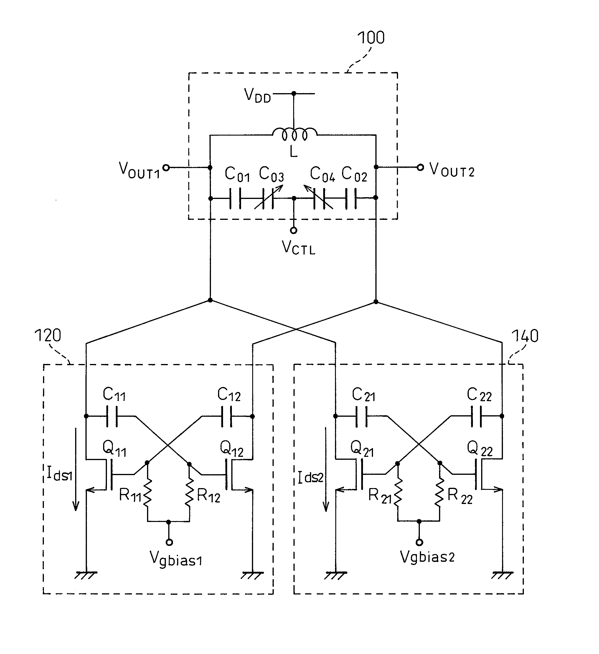
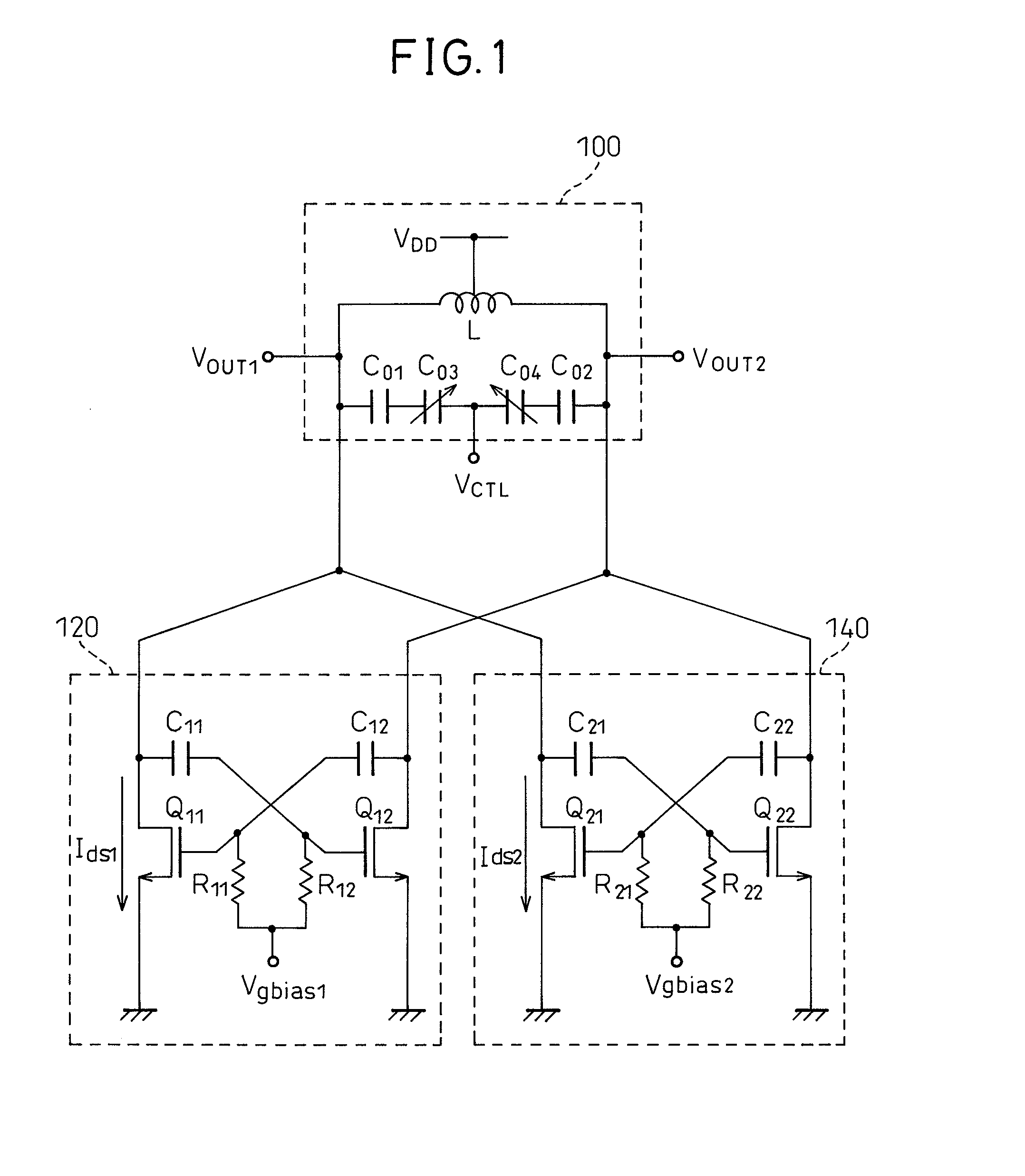
[0023]The embodiments of the present invention will be described below with reference to the accompanying drawings. FIG. 1 is a circuit diagram showing one embodiment of a voltage-controlled oscillator (VCO) according to the present invention. As shown in FIG. 1, the VCO includes an LC parallel resonant circuit (LC tank circuit) 100, a first amplifier circuit 120, and a second amplifier circuit 140.

[0024]The LC parallel resonant circuit 100 is essentially a loop, which as shown in FIG. 1, includes an inductor L, two fixed capacitors C01 and C02, and two variable capacitors C03 and C04. An intermediate tap on the inductor L is connected to a supply voltage VDD. The capacitances of the variable capacitors C03 and C04 vary with a control input voltage VCTL which is applied to their input terminals via a node connecting between them. The two ends of the inductor L are connected to output terminals which provide the two output signal voltages VOUT1 and VOUT2 of the VCO.

[0025]The first an...


PUM


Abstract

A voltage-controlled oscillator that can achieve low phase noise while ensuring stable oscillation startup and stable oscillation maintenance even under low supply voltage conditions. The voltage-controlled oscillator includes an LC parallel resonant circuit, whose impedance varies with a control input voltage and a negative resistance circuit for introducing negative resistance into the LC parallel resonant circuit, wherein the negative resistance circuit includes at least: a first amplifier circuit, provided in parallel with the LC parallel resonant circuit and having a first pair of transistors cross-coupled via a capacitor, that achieves class-C amplifier operation by biasing the gate of each transistor in the first transistor pair with a first bias voltage; and a similarly configured second amplifier circuit that achieves class-C amplifier operation by biasing the gate of each transistor with a second bias voltage which is different from the first bias voltage.

Description

[0001]This application claims benefit of Serial No. 2006-121248, filed 19 May 2009 in Japan and which application is incorporated herein by reference. To the extent appropriate, a claim of priority is made to the above disclosed application.BACKGROUND OF THE INVENTION[0002]1. Field of the Invention[0003]The present invention relates to a voltage-controlled oscillator (VCO), which oscillates at a frequency proportional to a control input voltage, and more particularly to an LC-tank voltage-controlled oscillator (LC-VCO).[0004]2. Description of the Related Art[0005]The phase noise of an LC-tank voltage-controlled oscillator is determined by the S / N ratio (Signal-to-Noise Ratio) in the LC tank. The root mean square values of signal voltage Vsig and noise voltage Vn are respectively expressed asVsig2=Rt2Isig2 Vn2=4kTRt where k is the Boltzmann constant, T is the absolute temperature, Rt is the parallel impedance of the LC tank, and Isig is the signal current amplitude.[0006]Hence, the r...

Claims


Application Information

Patent Timeline
IPC IPC(8): H03B5/12
CPCH03B5/1228H03B5/1243H03B5/1212
Inventor OKADA, KENICHI
Owner SEMICON TECH ACADEMIC RES CENT
Why Eureka
Try Eureka