Rotor for reluctance type rotating machine

a technology of electric rotating machines and rotors, which is applied in the direction of dynamo-electric machines, magnetic circuit rotating parts, magnetic circuit shape/form/construction, etc., can solve the problems of vibration noise, vibration ripple, oscillation, etc., and achieve the effect of reducing the harmonic value of the counter electromotive for

Active Publication Date: 2006-06-06
TOSHIBA INFRASTRUCTURE SYST & SOLUTIONS CORP +2
View PDF10 Cites 29 Cited by
  • Summary
  • Abstract
  • Description
  • Claims
  • Application Information

AI Technical Summary

Benefits of technology

[0012]A magnetic torque by the permanent magnets can also be achieved in addition to reluctance torque. Furthermor

Problems solved by technology

It is well known that squirrel-cage induction motors result in crawling due to torque developed by high harmonics.
There is a possibility that permanent-magnet reluctance type rotating machines as the r

Method used


Image

  • Rotor for reluctance type rotating machine
  • Rotor for reluctance type rotating machine
  • Rotor for reluctance type rotating machine

Examples


Embodiment Construction

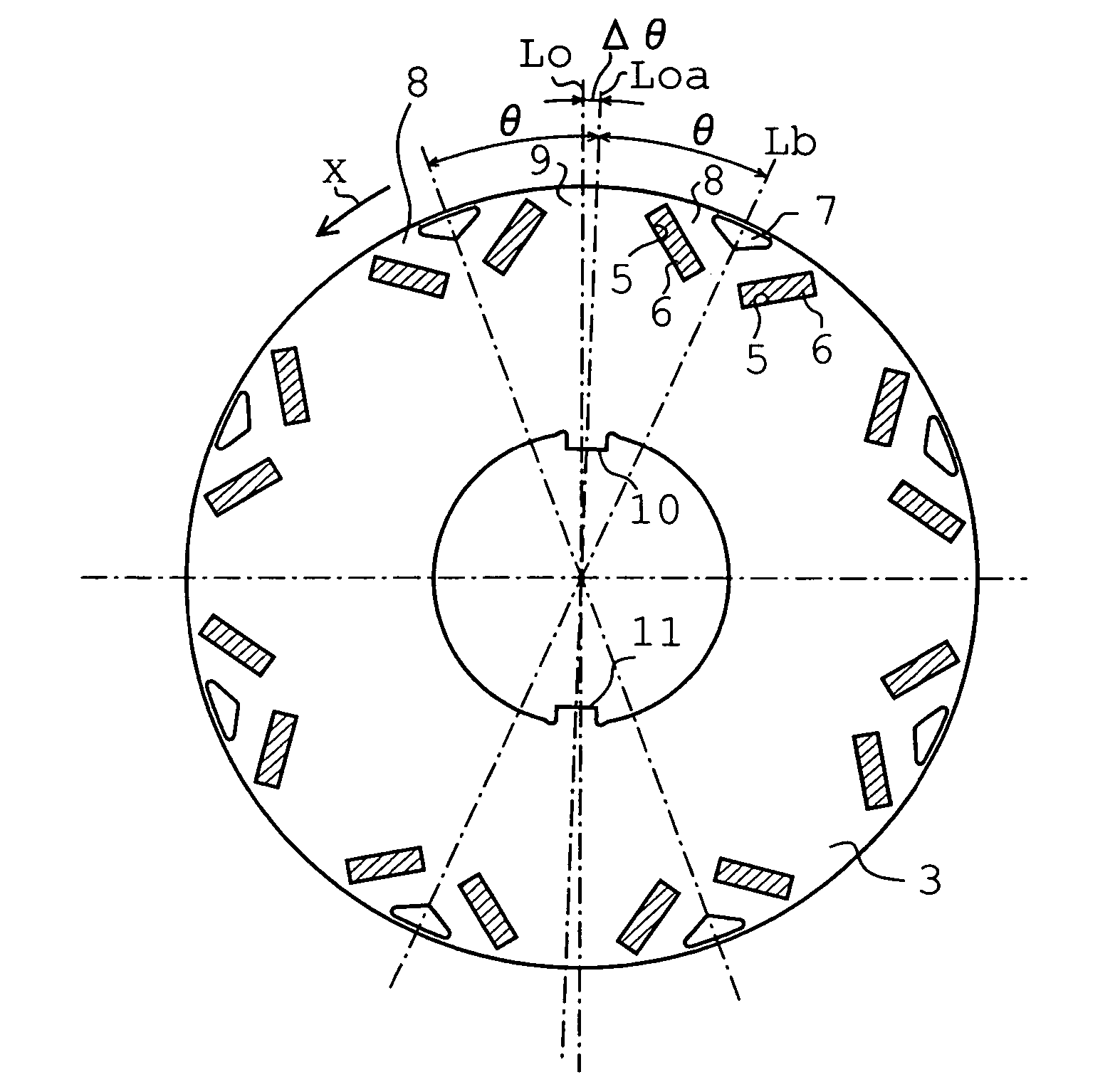
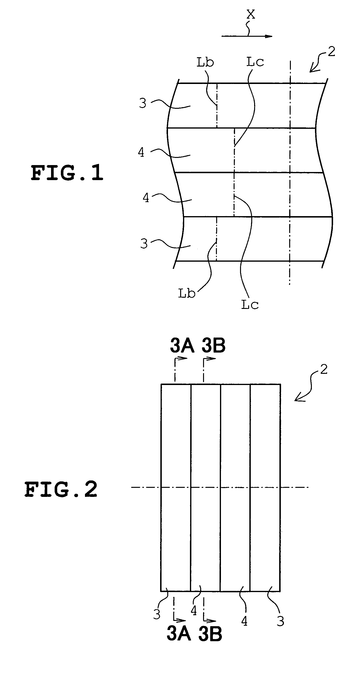
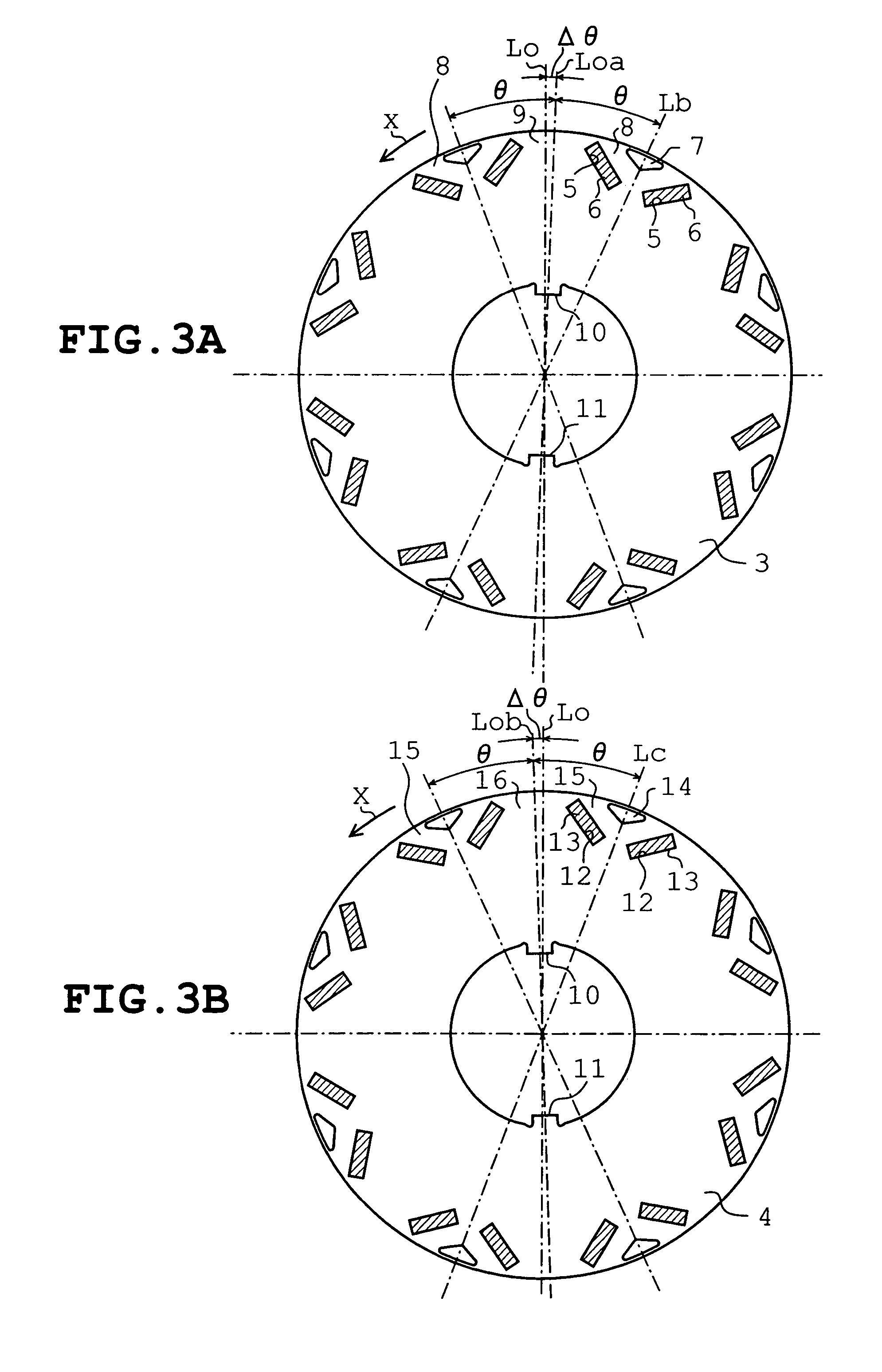
[0022]FIGS. 1 to 5 illustrate an embodiment in which the invention is applied to a reluctance type rotating machine with permanent magnets. The reluctance type rotating machine possesses eight poles. A rotor 1 of the reluctance type rotating machine includes a rotor core 2 made by stacking a number of annular silicon steel sheets serving as a core material. The rotor core 2 is divided into four blocks 3 and 4 having the same thickness as shown in FIG. 2. The blocks 3 and 4 are stacked in order of 3, 4, 4 and 3.

[0023]Each block 3 or the silicon steel sheets composing each block 3 will be described with reference to FIG. 3A. Each block 3 has a number of pairs of generally rectangular magnet insertion holes 5 formed in an outer circumferential portion thereof. The paired magnet insertion holes 5 are opposed to each other so that a distance therebetween is gradually increased as the magnet insertion holes 5 near an outer circumferential edge. Permanent magnets 6 are inserted into the pa...


PUM


Abstract

A rotor for a reluctance type rotating machine includes a rotor core formed by stacking a number of annular core materials each of which includes magnetic concave and convex portions alternately formed on an outer circumference thereof and a central through hole, the rotor core having a key axially extending on an outer circumference, the rotor core being divided into a plurality of blocks, the core materials constituting one of at least three blocks having the magnetic concave and convex portions shifted by a predetermined angle in one of a rotating direction of the rotor and a direction opposite the rotating direction of the rotor relative to a center line passing the key, the core materials constituting each one of the blocks located at both ends of the one block having the magnetic concave and convex portions shifted by a predetermined angle in the other of the rotating direction of the rotor and the direction opposite the rotating direction of the rotor relative to a center line passing the key, and a rotational shaft inserted through the central hole of the rotor core, the shaft having a key groove engaging the key of the rotor core.

Description

BACKGROUND OF THE INVENTION[0001]1. Field of the Invention[0002]This invention relates to a rotor for a reluctance type electric rotating machine which can achieve the similar effects to those achieved by skew.[0003]2. Description of the Related Art[0004]A reluctance type rotating machine or, for example, a reluctance type rotating machine provided with permanent magnets includes a rotor formed with a magnetic convex portion where a flux is easy to pass (d axis) and a magnetic concave portion where a flux is difficult to pass (q axis) and a permanent magnet which is disposed in a stator provided with a stator winding. The magnetic convex portion (d axis) has a high magnetic flux density in an air gap, whereas the magnetic concave portion (q axis) has a low magnetic flux density in an air gap. These variations in the magnetic flux density produce reluctance torque. Furthermore, torque is also developed by a magnetic attractive force and a magnetic repulsive force between poles of the...

Claims


Application Information

Patent Timeline
IPC IPC(8): H02K1/27H02K21/14H02K21/12H02K19/10
CPCH02K1/2766
Inventor ARAKI, TAKASHIMATSUBARA, MASAKATSUMOCHIZUKI, MOTOYASUKAZAO, YUKIHIKOARATA, MASANORIHIRANO, YASUOAIKURA, NOBUTAKEKONDO, AKITOYAMASHIKI, MASAHIKOOHASHI, MASANORIHANAI, TAKASHITAKEDA, KENMOROHASHI, HIROSHI
Owner TOSHIBA INFRASTRUCTURE SYST & SOLUTIONS CORP
Why Eureka
Try Eureka