Laser welding device and laser welding method

a laser welding and laser welding technology, applied in the direction of welding devices, soldering devices, manufacturing tools, etc., can solve the problems of increasing the number of constituent elements, increasing the installation cost of such welding equipment, and increasing the maintenance cost of such components, so as to achieve sufficient melting depth, increase the melting depth, and simplify the movement mechanism

Active Publication Date: 2020-08-04
HONDA MOTOR CO LTD
View PDF12 Cites 0 Cited by
  • Summary
  • Abstract
  • Description
  • Claims
  • Application Information

AI Technical Summary

Benefits of technology

[0019]With the invention according to claim 1, the focal point of the laser beam is drawn in the form of a helix, and a central axis of the helix is formed along the curved surface. The helix overlaps itself at locations distanced from the apex of the curved surfaces in the workpieces. When performed in this manner, a semi-solidified portion is re-melted, and the re-melted portion becomes a semi-solidified portion, and by repeating the re-melting of the semi-solidified portion again and again, the melting depth increases. Thus, even at ends of the curved surface, a sufficient melting depth can be obtained.
[0020]According to the present invention, despite the welding sites existing on a curved surface, the laser irradiation mechanism can be moved linearly. Due to such linear motion, the moving mechanism is simplified and is small in scale. Thus, by the present invention, a laser welding device is provided, which is both simple in structure and small in scale, even for a device in which curved surfaces are welded.
[0021]With the invention according to claim 2, when the laser beam passes through an apex of the curved surface, the control unit causes the laser beam to be perpendicular to a tangent line that passes through the apex, and causes the laser beam to incline toward a center of curvature of the curved surface at welding sites that are distanced from the apex of the curved surface. The laser irradiation mechanism includes a function to cause the laser beam to incline if the laser beam resides within a fixed range. By utilizing this function skillfully, the laser beam is made to incline toward the center of curvature of the curved surface at welding sites that are distanced from the apex of the curved surface. Owing to such inclination, the overlapping of the helix with itself can be mitigated, and productivity can be enhanced.

Problems solved by technology

As a result, installation costs for such welding equipment increase.
In addition, since the structure is complex, the number of constituent elements increases, and maintenance costs that occur accompanying the replacement of such components tend to rise precipitously.

Method used


Image

  • Laser welding device and laser welding method
  • Laser welding device and laser welding method
  • Laser welding device and laser welding method

Examples


embodiment

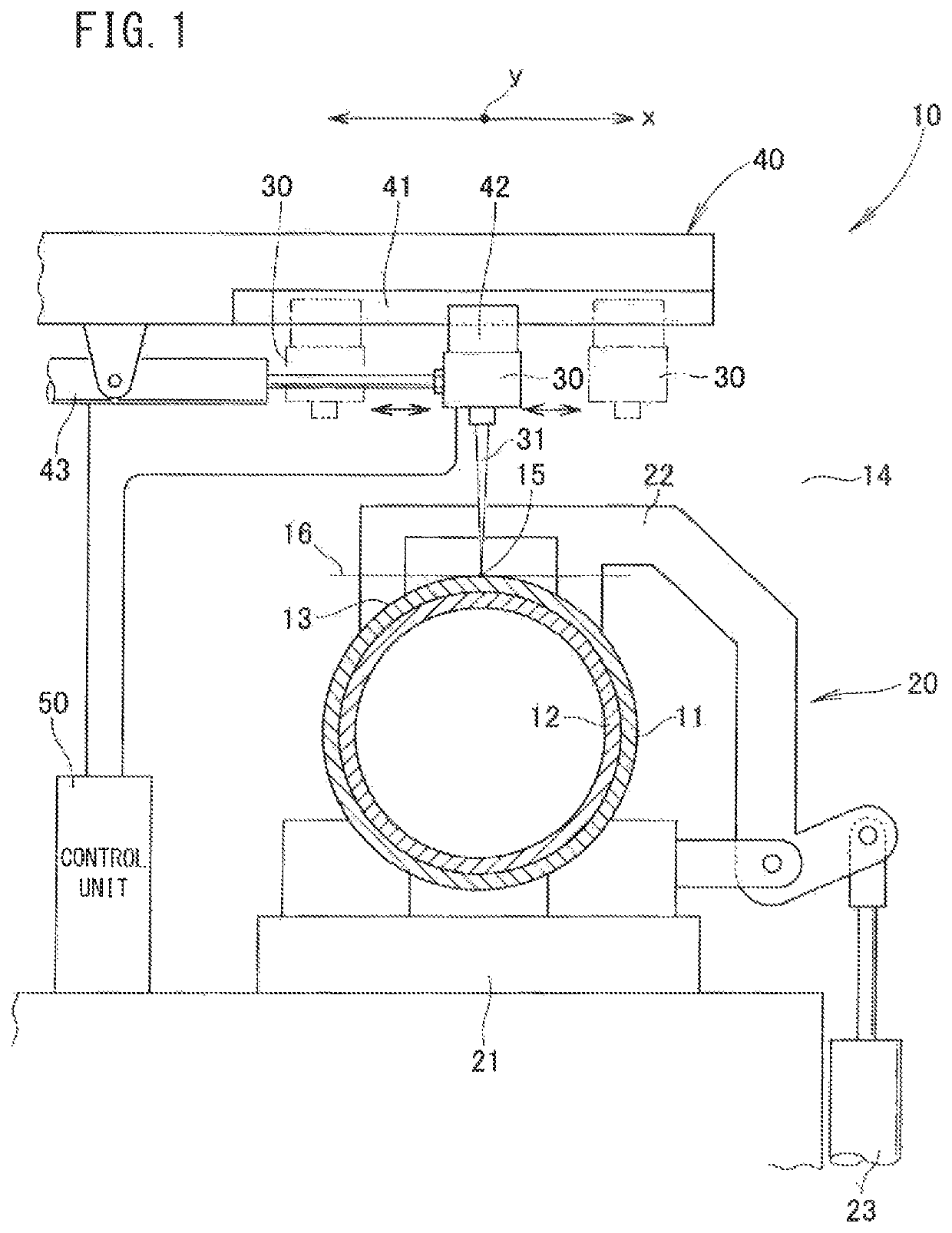
[0032]As shown in FIG. 1, a laser welding device 10 comprises a workpiece fixing unit 20 that presses and fixes workpieces 11, 12, a laser irradiation mechanism 30 that irradiates a laser beam 31 toward the workpieces 11, 12, a moving mechanism 40 that moves the laser irradiation mechanism 30 linearly, and a control unit 50 that serves to control the laser irradiation mechanism 30 and the moving mechanism 40. Below, an example of a configuration of the respective constituent elements will be described.

[0033]The workpieces 11, 12 are constituted from a cylindrical first workpiece 11, and a cylindrical second workpiece 12 that is inserted into the first workpiece 11. A curves surface of the second workpiece 12 is superimposed on a curved surface of the first workpiece 11.

[0034]In the present invention, the curved surfaces are joined with each other, and welding sites 13 thereof exhibit a circular arcuate shape. A plane 14 that passes through such welding sites 13 coincides with the pl...


PUM

PropertyMeasurementUnit
angleaaaaaaaaaa
center of curvatureaaaaaaaaaa
energy densityaaaaaaaaaa

Abstract

This laser irradiation mechanism includes a control unit which has a function allowing the focal point of a laser beam to describe a circle, performs control such that the focal point describes a spiral, and performs control such that the central axis of the spiral moves along a curved surface.

Description

TECHNICAL FIELD[0001]The present invention relates to a laser welding device and a laser welding method.BACKGROUND ART[0002]A second member is placed in abutment against a first member. An abutment site between the members is welded. From the conventional art, it is widely known to carry out such welding in order to unite the two members in an integral manner.[0003]In carrying out welding, in recent years, a laser beam with high energy density has been used.[0004]With such a laser beam, a technique is known in which curved surfaces are welded together (for example, refer to Patent Document 1).[0005]The technique of Patent Document 1 will be described with reference to FIG. 9.[0006]As shown in FIG. 9, two steel pipes 101, 101 are oriented in front and rear directions of the drawing and are placed together in abutment. The steel pipes 101 are surrounded by an annular guide rail 102. A processing head 103 is mounted movably on the guide rail 102. A laser gun 104 is mounted on the proce...

Claims


Application Information

Patent Timeline
Patent Type & Authority Patents(United States)
IPC IPC(8): B23K26/04B23K26/32B23K26/282B23K26/244B23K37/04B23K26/08B23K26/082B23K101/06B23K101/10B23K103/04B23K103/10B23K103/14
CPCB23K26/082B23K26/04B23K26/244B23K26/0869B23K26/282B23K26/08B23K26/32B23K26/048B23K37/0443B23K2103/04B23K2101/10B23K2103/10B23K2101/06B23K2103/05B23K2103/14
Inventor AKAHOSHI, HIDEAKIFUJIKURA, KOTARONEMOTO, CHIYOKOTAMURA, YUICHIROHASHIMOTO, KEN
Owner HONDA MOTOR CO LTD
Why Eureka
Try Eureka