Pressing device of card connector

A card connector and memory card technology, which is applied to the parts of the connecting device, the device for connecting/disconnecting the connecting parts, the connection, etc., can solve the problems of excessive upper and lower gaps, poor contact, and loss of the memory card and the conductive terminals.

Inactive Publication Date: 2006-11-01
ALLTOP TECH CO LTD
View PDF0 Cites 1 Cited by
  • Summary
  • Abstract
  • Description
  • Claims
  • Application Information

AI Technical Summary

Problems solved by technology

[0004] However, this structural design allows the memory card to form electrical contact with each conductive terminal when the memory card is pushed in. When the memory card is inserted, the memory card will deform the conductive terminals under pressure, and the conductive terminals have An elastic reset force is used to resist the memory card to form an electrical resistance state, and the conductive terminal will gradually lose its elastic reset force as the memory card is used for a long time or the number of repeated plugging and unplugging increases. It resists the memory card, and when the insulating base is moved or impacted, the memory card will shake, which will easily cause poor contact and generate noise. When the elastic fatigue is serious, the upper and lower gaps between the memory card and the conductive terminal will be too large and cannot Form electrical contact, and then use the memory card. Moreover, because the current shielding shell is very thin, when the memory card is inserted into the insulating seat, the shielding shell is easily deformed, and the memory card Excessive upper and lower clearances from the conductive terminals will exacerbate the problem and make it unusable

Method used


Image

  • Pressing device of card connector
  • Pressing device of card connector
  • Pressing device of card connector

Examples


Embodiment Construction

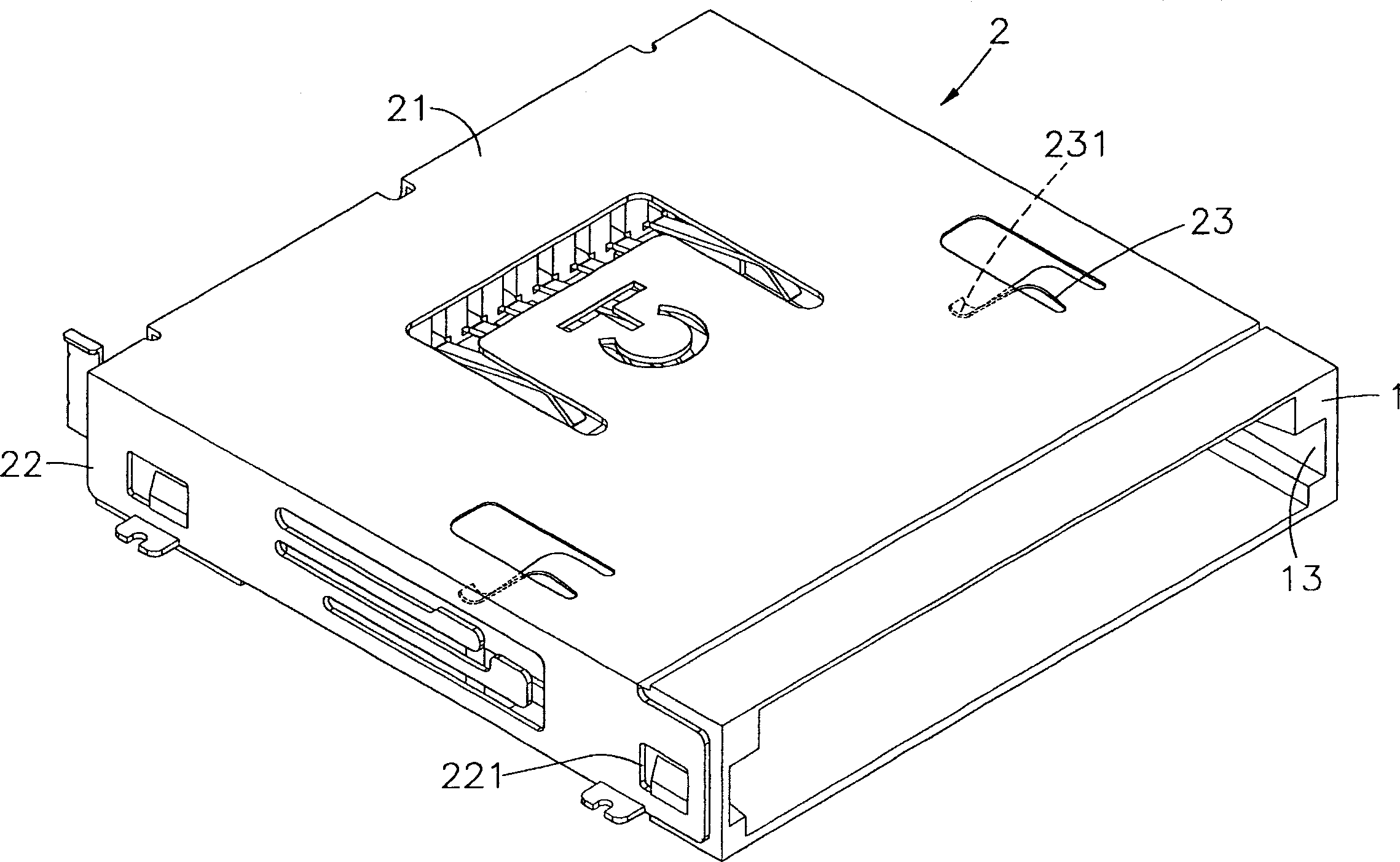
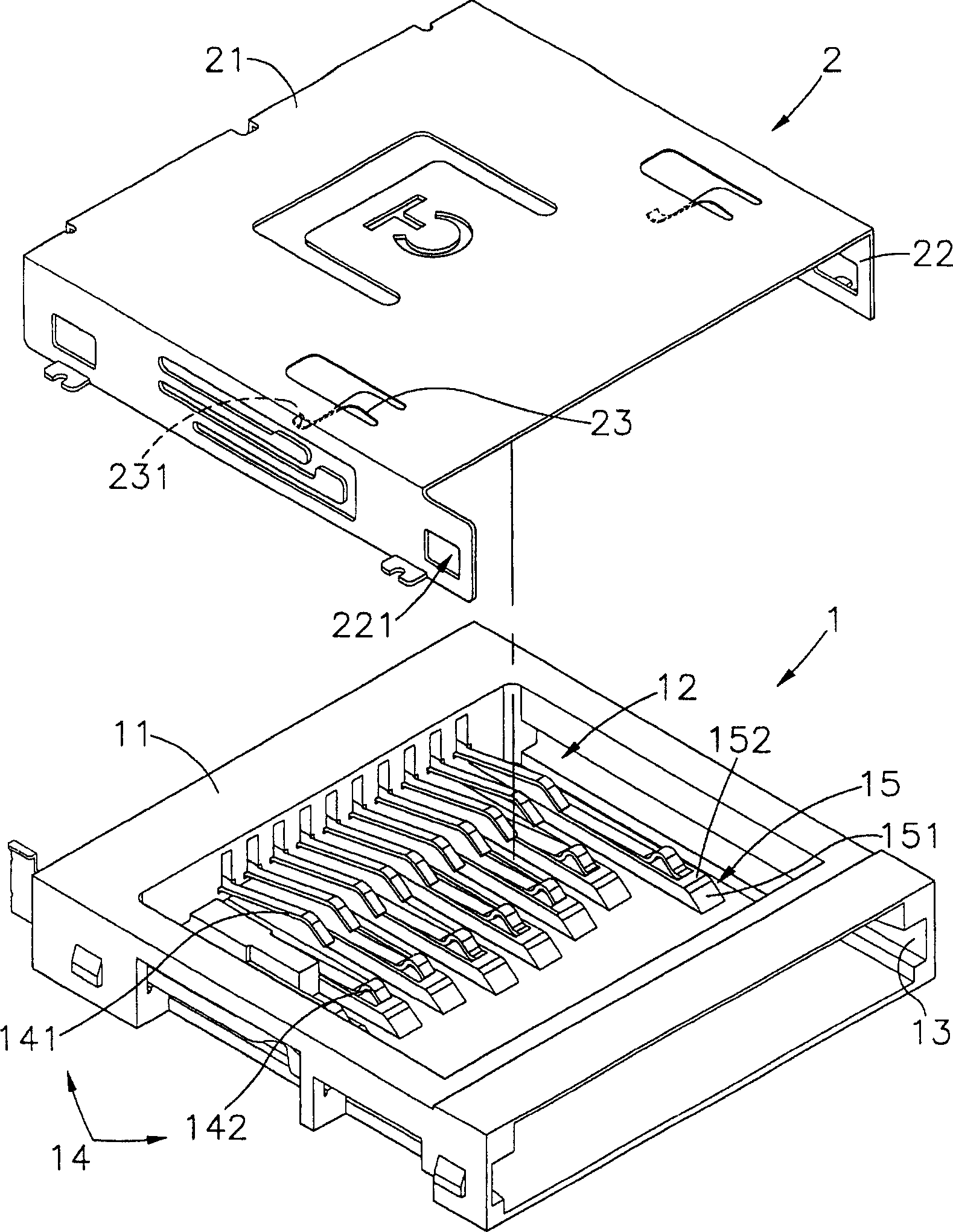
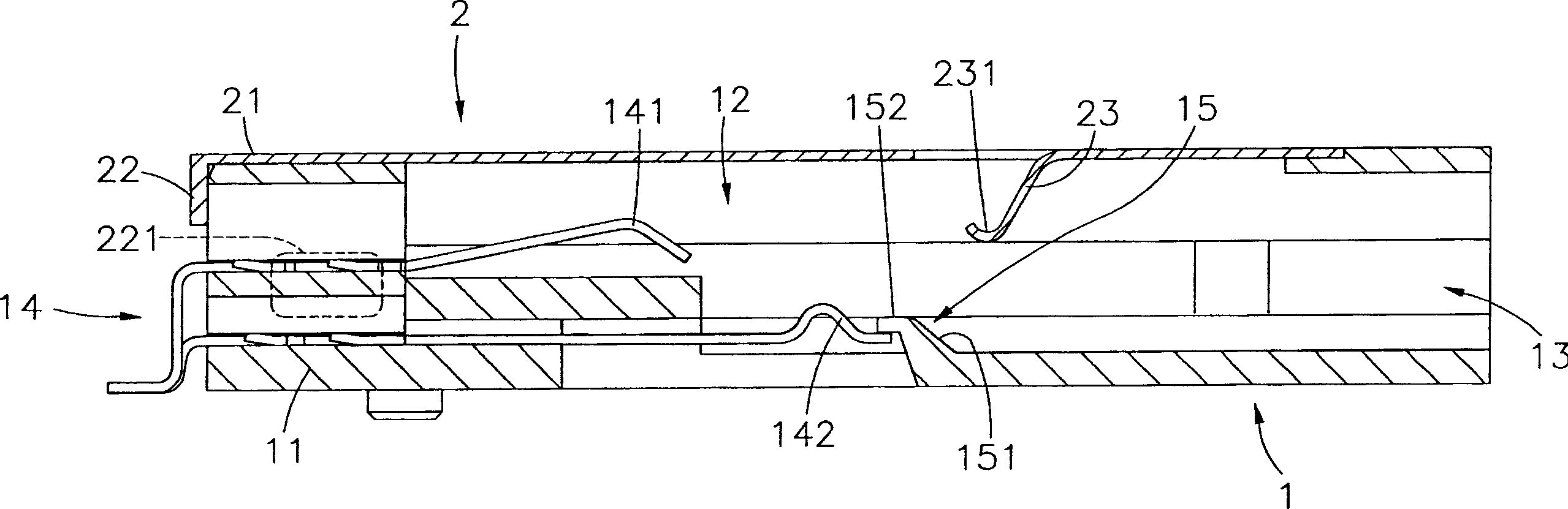
[0038] Please also see figure 1 , 2 , 3 are the three-dimensional appearance view, three-dimensional exploded view and side view section view of the present invention. It can be clearly seen from the figure that the card connector pressing device of the present invention includes an insulating seat body 1 and a shielding shell 2 Therefore, the main structural features of this case are described in detail below; among them:

[0039] The insulating seat body 1 has a base 11, and the base 11 has a docking space 12 that can be pushed into by different preset memory cards (not shown in the figure), and a slot 13 is provided on one side of the docking space 12, away from The other side of the slot 13 is provided with a plurality of terminal groups 14, and the plurality of terminal groups 14 has at least one or more terminal groups, and each terminal group 14 is installed in the base 11 and is arranged in the docking space 12, and the plurality of terminal groups 14 The group 14 h...


PUM


Abstract

The invention comprises: an insulation seat and a shielding case. The insulation seat has a base in which there is a connecting space for holding different type of memory card. Beside one side of said connecting space there is a slot, and beside another side of said connecting space there is multi sets of posts located in said connecting space in said base. A basal unit is located in said shielding case, and the spring pieces are located at both sides of said basal unit and in the connecting space. When the memory card is inserted, the spring piece can press the memory card to form a barrier that secures the memory card on the set of posts.

Description

technical field [0001] The present invention provides a pressing device for a card connector, in particular, one or more shrapnels are provided on the surface of the shielding shell, so that when different memory cards are pushed into the docking space, a pressure can be generated by elastic pressing of the shrapnel. The pressure ensures that the memory card is in contact with the corresponding terminal group, the memory card does not shake and tilt, and a benign contact is formed. Background technique [0002] Since its inception, flash memory has gradually replaced EEPROM (Voltage Elimination Programmable Read-Only Memory) or batteries in many portable devices due to its attractive features such as powerful computing functions, fast speed, high expandability, and high storage density. For power supply memory, due to the current semiconductor technology is becoming more and more sophisticated, the storage density and transmission speed of flash memory have grown by leaps an...

Claims


Application Information

Patent Timeline
Patent Type & Authority Applications(China)
IPC IPC(8): H01R13/648H01R13/62H01R13/629
Inventor 苏朴传
Owner ALLTOP TECH CO LTD
Why Eureka
Try Eureka