Ball bearing

一种球轴承、轴承的技术,应用在球轴承领域,能够解决不能应用、高摩擦和磨损、减弱保持架强度等问题

Inactive Publication Date: 2011-04-20
SCHAEFFLER TECH AG & CO KG
View PDF2 Cites 0 Cited by
  • Summary
  • Abstract
  • Description
  • Claims
  • Application Information

AI Technical Summary

Problems solved by technology

Such contact between the bearing race and the cage produces undesirably high friction and wear
The material through which the cage is pierced by a plurality of small holes, while facilitating the delivery of lubricant to the guide surfaces, also detrimentally weakens the strength of the cage
Such cages have only limited or no application in very high speed bearings

Method used


Image

  • Ball bearing
  • Ball bearing
  • Ball bearing

Examples


Embodiment Construction

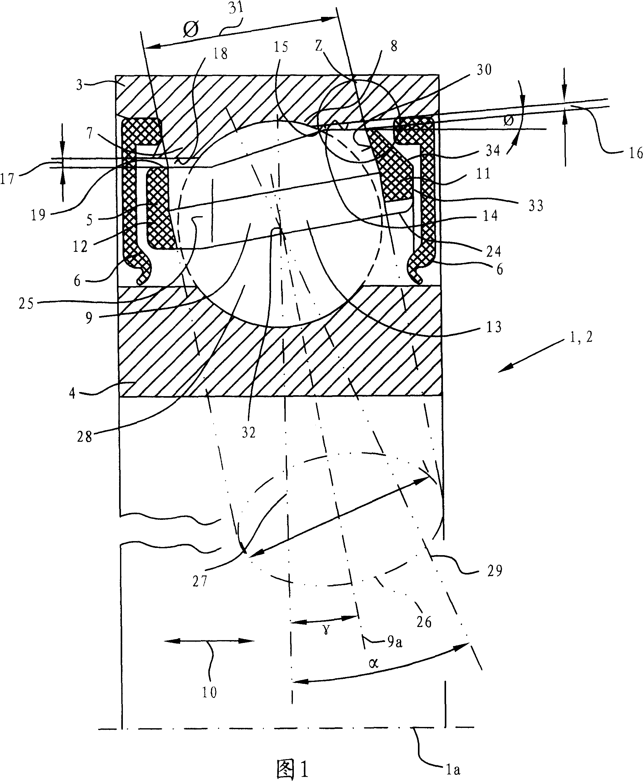
[0021] FIG. 1 shows a longitudinal section of an exemplary embodiment of a ball bearing 1 in the form of an angular contact ball bearing 2 for a spindle bearing, taken along the axis of rotation 1 a of the ball bearing. The ball bearing 1 has an outer ring 3 , an inner ring 4 and a cage 5 and is provided with a seal 6 . Shoulders 7 and 8 are formed on outer ring 3 . Compared with the low shoulder 8 , the high shoulder 7 protrudes to a greater extent radially in the direction of the axis of rotation relative to the bearing race 3 .

[0022] The cage 5 is provided on the circumferential side with pockets 9 adjoining one another about the axis of rotation 1 a of the ball bearing 1 , of which only one pocket 9 is shown in the illustration according to FIG. 1 and is longitudinally sectioned. Each pocket 9 is bounded in an axial direction indicated by a double arrow 10 by a first rib 11 and in a direction opposite to the first direction by a second rib 12 . Laths 13 extend between...


PUM


Abstract

The invention relates to a ball bearing (1) provided with a bearing ring (3,4) and a cage (5, 35), in addition to at least one run-on surface (15) which is mounted on the bearing ring (3,4). The cage (5, 35) is provided with pockets (9, 41) which are adjacent to each other and which are arranged on the side of the periphery around the rotational axis (1a, 35a) of the ball bearing (1). Each pocket(9, 41) is defined in a demodulated axial first direction of the first edge (11, 36) by means of the axis of rotation (1a, 35a), in addition to being at least partially defined in at least one seconddirection of the second edge (12, 37) which is counter to the first direction, and at least one of the edges (11, 12, 36, 37) is defined in a radial direction by a radial guide surface (14, 45), whereby the guide surface (14,45) lies opposite the run-on surface (15) in at least a radially defined manner.

Description

technical field [0001] The invention relates to a ball bearing comprising a bearing race and a cage and at least one thrust surface on the bearing race wherein the cage is provided with pockets adjacent to each other on the circumferential side around an axis of rotation of the ball bearing, and each pocket is partially bounded in a first axial direction co-directional with the axis of rotation by a first rib and at least partially bounded by a second rib in at least one second direction opposite to the first direction, and at least one of the ribs is bounded in a radial direction by a radial guide surface, wherein the guide surface is at least dia. Face the thrust face. Background technique [0002] The invention relates to all conceivable embodiments of ball bearings in which the balls are guided in a cage and the ribs of the cage are offset radially relative to one another. The invention also relates in particular to angular contact ball bearings with symmetrical and / o...

Claims


Application Information

Patent Timeline
Patent Type & Authority Patents(China)
IPC IPC(8): F16C19/16F16C33/38F16C33/58
CPCF16C33/3856F16C33/6651F16C19/163F16C19/14F16C33/58F16C33/3806F16C33/583F16C2322/39
Inventor O·拜尔O·黑尔特林
Owner SCHAEFFLER TECH AG & CO KG
Why Eureka
Try Eureka