
Impeller with an abradable tip

An impeller and blade technology, applied in the field of impellers that significantly improve the pumping efficiency, can solve the problems of the circulating fluid not being replaced or being sufficiently filtered, reducing the pumping efficiency, etc.

Inactive Publication Date: 2007-10-10
金属达因有限责任公司
View PDF0 Cites 0 Cited by
  • Summary
  • Abstract
  • Description
  • Claims
  • Application Information

AI Technical Summary

Problems solved by technology

Typical low-cost metal stamping processes are difficult to maintain such tight tolerances
Therefore, the clearance between the impeller blades and the casing is often larger than necessary, thereby reducing the efficiency of the pump
[0007] Additionally, many hydraulic pumps operate in a closed system where the circulating fluid is not replaced or adequately filtered

Method used


Image

  • Impeller with an abradable tip
  • Impeller with an abradable tip
  • Impeller with an abradable tip

Examples


Embodiment Construction

[0022] Although the present invention has been described in terms of such a preferred mode of application of the invention as applied to a centrifugal water pump of an internal combustion engine, those skilled in the art will appreciate that the present invention is applicable to many liquid cycle applications, whether closed or open system. Accordingly, neither the preferred applications described in this specification nor the several alternative embodiments of this specification should limit the scope of the invention, departing from the invention as particularly recited in the appended claims.

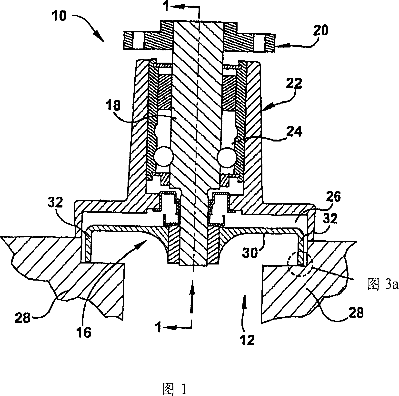
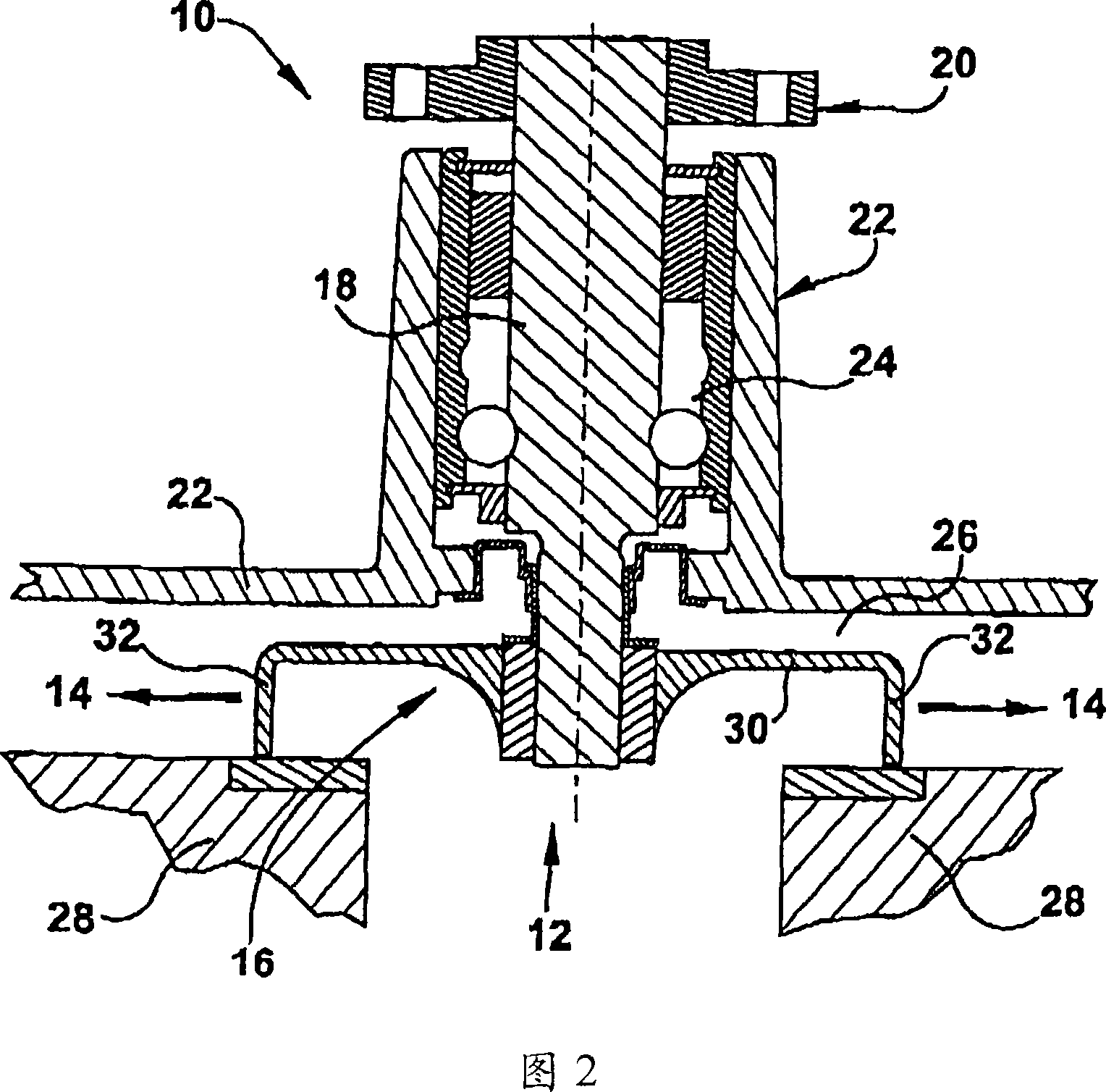
[0023] Referring now to the drawings, and particularly to FIGS. 1 and 2, a partial cross-section of a single-stage centrifugal pump 10 is shown. The pump 10 is positioned between an inlet hole 12 and an outlet hole 14 to force liquid from the water inlet hole 12 to the outlet hole 14 . The pump 10 includes an impeller 16 mounted on the end of a drive shaft 18 which is then connecte...


PUM


Abstract

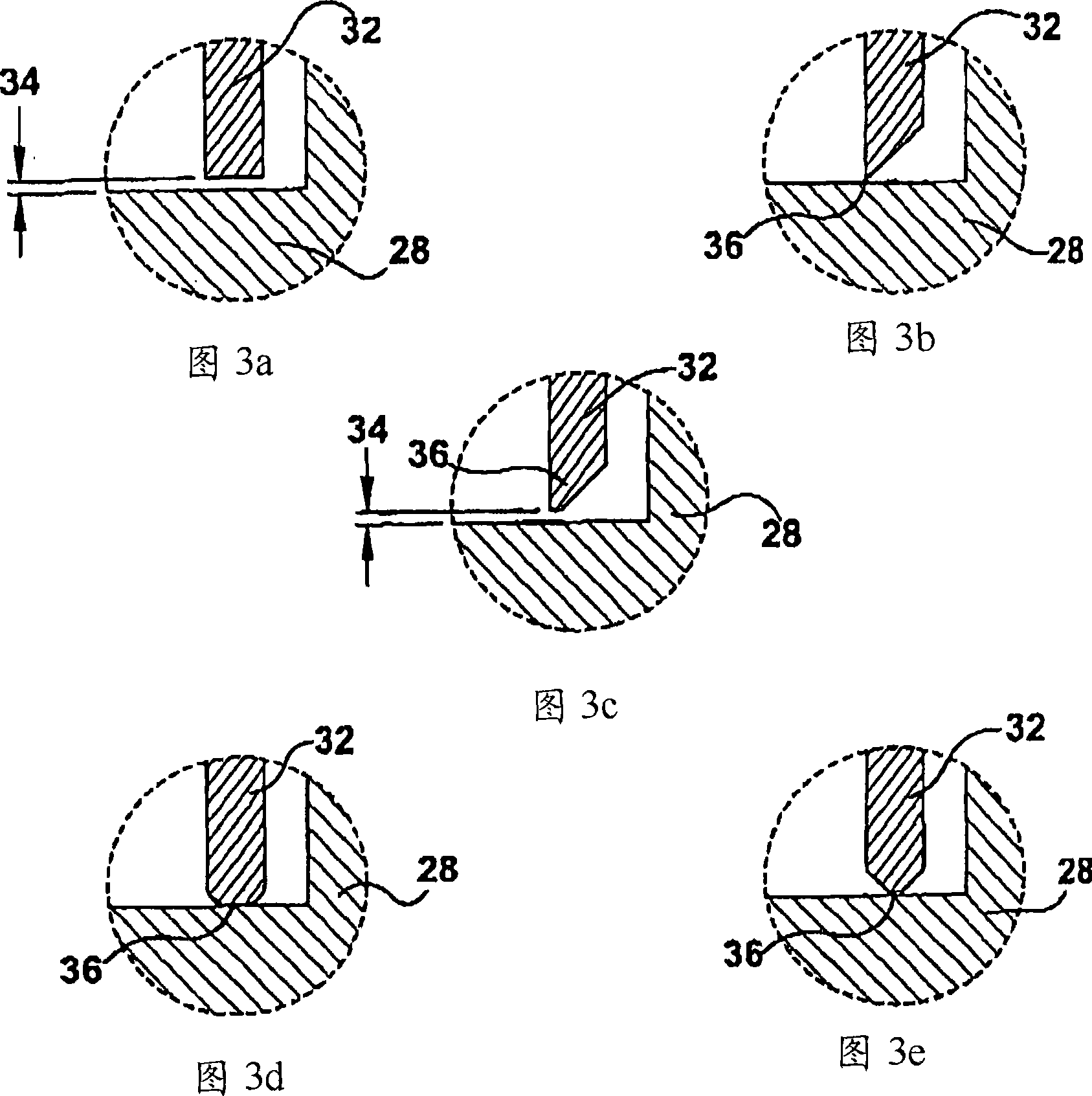
An impeller for moving liquid through a pump system having a body, at least one vane extending from the body and capable of moving liquid through the system during rotation thereof, and a tapered, abradable tip extending from the vane wherein, during rotation of said body, the tapered end of abradable tip wears away in response to contact with the pump housing to produce a reduced amount of abradable material circulating through the system while providing nominal operational clearance between the tip and the housing to improve pumping efficiency.

Description

[0001] CROSS-REFERENCE TO RELATED APPLICATIONS [0002] This application claims priority to US Provisional Patent Application No. 60 / 611,456, filed September 20, 2004, the disclosure of which is incorporated herein by reference in its entirety. technical field [0003] The present invention relates generally to impellers for liquid pumps, and more particularly to an impeller with abradable tips for significantly increasing pumping efficiency. Background technique [0004] Centrifugal pumps known in the art generally include inlet and outlet pipes separated by a plenum with an impeller set. Typically, the impeller includes a disk having a plurality of radially spaced blades. The impeller is mounted on the end of a drive shaft driven by an external motor. When driven by the drive shaft, the impeller blades transfer kinetic energy to the liquid in contact therewith. These kinetic energies cause an increase in pressure, which then causes the liquid to flow from the inlet pipe...

Claims


Application Information

Patent Timeline
Patent Type & Authority Applications(China)
IPC IPC(8): F01D5/00
CPCF04D29/628F04D29/622
Inventor D·塔耶J·克里德
Owner 金属达因有限责任公司
Learn More