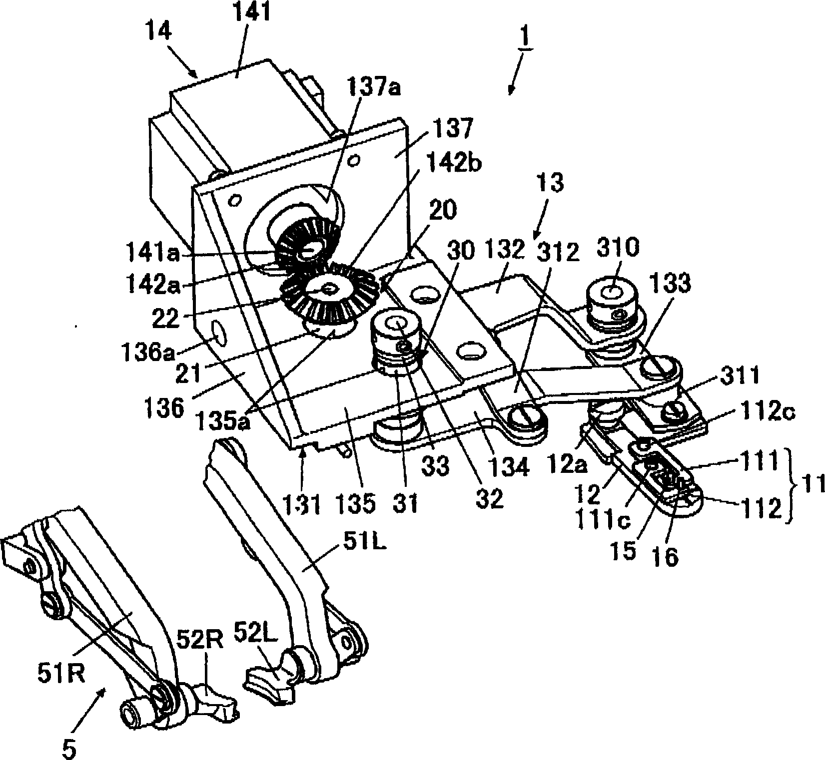
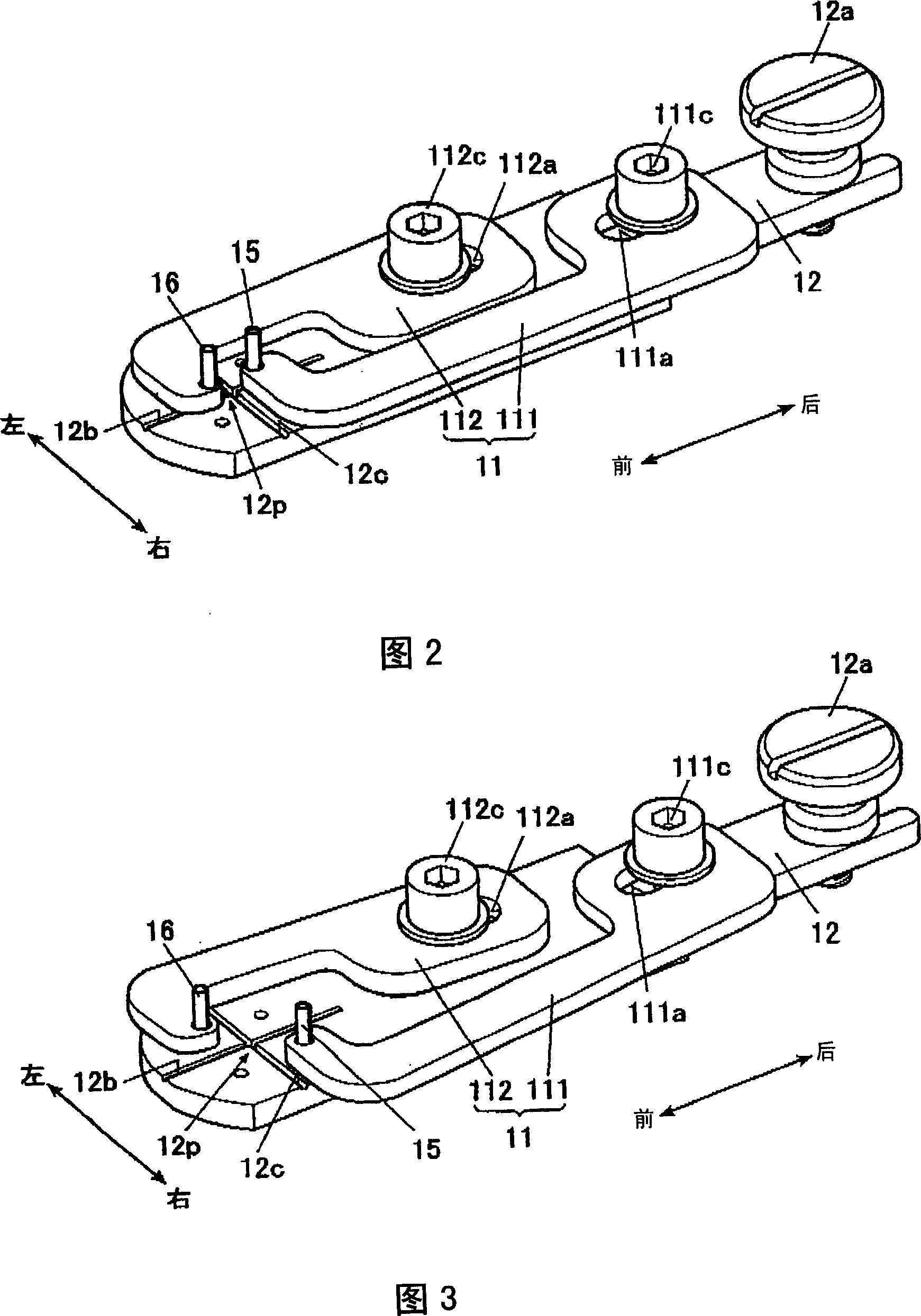
Button conveying device
A conveying device and button technology, which is applied to textiles, papermaking, sewing equipment, etc., can solve the problems of increasing the cost of the button placing table, lowering the work efficiency, and difficulty in parts management, so as to reduce the burden of replacement operations and parts management, reduce Quantity, the effect of saving resources
- Summary
- Abstract
- Description
- Claims
- Application Information
AI Technical Summary
Problems solved by technology
Method used
Image
Examples
Deformed example 1
[0101] For example, when having Figure 9 In the case of a button with 2 threading holes H1, H3 shown in (a), it can also be configured as Figure 10 The button conveying device 6 shown.
[0102] The button conveyance device 6 has a plate-shaped mounting table 61 . The mounting table 61 is arranged along the front-rear direction of the button conveying device 6 in its longitudinal direction. A mounting hole 61 a for mounting the pinion gear 62 is formed substantially in the center of the mounting base 61 , and is mounted to the mounting base 61 using screws 68 . On the mounting platform 61, a button loading platform 60 is provided, and the button loading platform 60 consists of a plurality of (in the Figure 10 2 in the middle) button loading arms 63,64 constitute.
[0103] Moreover, on the upper surface of the mounting base 61, two guide parts 61b which pinch|interpose the button mounting arms 63 and 64 from the outside are formed in the side edge of the mounting base 61....
Deformed example 2
[0114] In addition, in Figure 9 In the case of buttons H1 to H4 with 4 threading holes shown in (b), it is also possible to use Figure 11 The button conveying device 7 shown.
[0115] The button conveyance device 7 has a plate-shaped mounting table 71 . The mounting table 71 is arranged along the front-rear direction of the button conveying device 7 in its longitudinal direction. A mounting hole 71 a for mounting the pinion gear 72 is formed substantially in the center of the mounting base 71 , and is mounted to the mounting base 71 with screws 78 . On the top of the mounting platform 71, a button loading platform 70 is provided. Figure 11 2 in the middle) button loading arms 73,74 constitute.
[0116] Moreover, two guide parts 71b which pinch|interpose button mounting arms 73 and 74 from the outside are formed in the upper surface of the mounting base 71. As shown in FIG. The space sandwiched between the guide parts 71b by the two guide parts 71b functions as a guide ...
Deformed example 3
[0127] Additionally, in order to be able to load such as Figure 9 A button with 2 threading holes H1, H3 as shown in (a), or Figure 9 Any of the buttons shown in (b) with four threading holes H1 to H4 can also be used Figure 12 The button conveying device 8 shown.
[0128] The button conveyance device 8 has a plate-shaped mounting table 81 . The mounting table 81 is arranged along the front-rear direction of the button conveying device 8 in its longitudinal direction. An attachment hole 81a for attaching the button mounting arms 83 and 84 is formed substantially at the center of the attachment base 81 . And the button mounting arms 83 and 84 which comprise the button mounting base 80 are attached to the mounting base 81 with the screw 88. As shown in FIG.
[0129] Moreover, two guide parts 81b which pinch|interpose the button mounting arm 83 are formed in the side edge along the longitudinal direction of the mounting base 81. As shown in FIG. The space sandwiched between...
PUM
 Abstract
Description
Claims
Application Information
 - R&D
- Intellectual Property
- Life Sciences
- Materials
- Tech Scout
- Unparalleled Data Quality
- Higher Quality Content
- 60% Fewer Hallucinations
Browse by: Latest US Patents, China's latest patents, Technical Efficacy Thesaurus, Application Domain, Technology Topic, Popular Technical Reports.
© 2025 PatSnap. All rights reserved.Legal|Privacy policy|Modern Slavery Act Transparency Statement|Sitemap|About US| Contact US: help@patsnap.com


